

JELIO ENGINEERING INSIGHTS
Milling vs. Router vs. Guillotine: Choosing the Right PCBA Depaneling Method
Choose a PCB depaneling method by the separation mechanism and the real panel, not by a short machine label. JELIO’s catalog uses PCB Router for milling-cutter equipment and also uses Router depaneling machine for the JLO-C400/C600 roller V-cut product. This guide explains that naming context, then compares milling, roller V-cut, guillotine, integrated router-and-saw and UV laser options. Start with the drawing, component layout and material information, then use the relevant product page and a representative sample to decide which process belongs on your equipment shortlist.
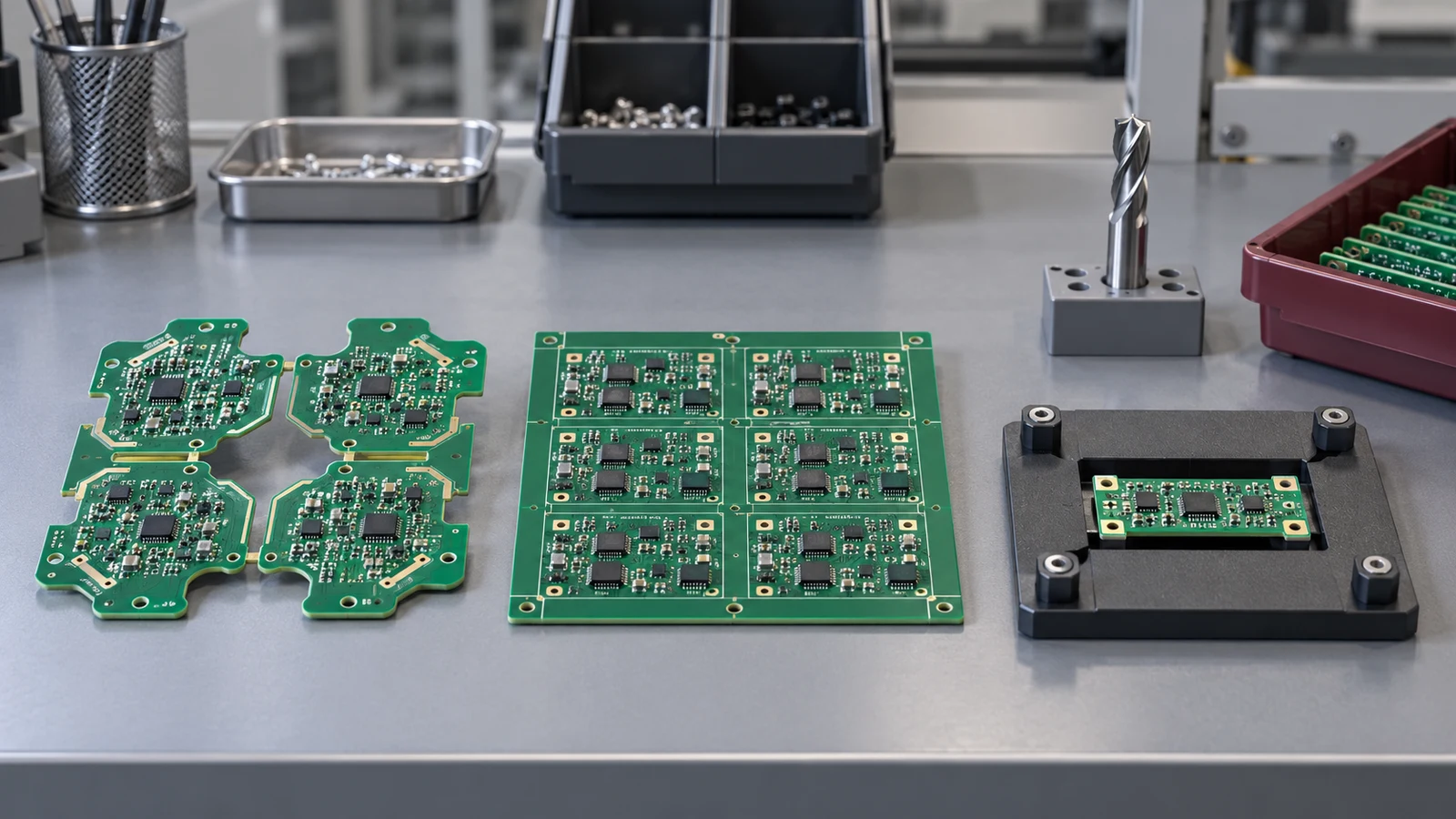
Which PCB depaneling method fits my panel?
Start with the board outline and whether separation follows tabs, a programmed contour or straight V-score lines. Then review component clearance, material and thickness, required edge condition and output handling. Compare each candidate with its own catalog limits. Milling/router, roller V-cut, guillotine and UV laser use different mechanisms, so select the process through a drawing-led sample review rather than treating their names as equivalent.
1. Compare mechanisms before comparing product names
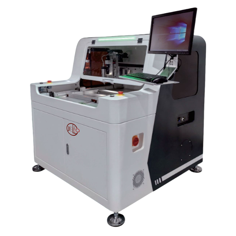
JELIO’s PCB Router Depaneling Machine pages describe a spindle and milling cutter following programmed paths. The JLO-C3532 / JLO-C5045 catalog lists straight, L-shaped, U-shaped, circular and arc functions. In this context, routing and milling refer to the spindle-based contour-cutting process described by those product pages.
The separate Router depaneling machine page describes JLO-C400/C600 equipment with an upper circular blade and lower straight blade for V-groove panels. That product title should not be used to assume that the machine has the same cutter path or contour capability as a milling-cutter PCB router. Read the mechanism, operation method and applicable-board fields together.
The distinction gives the original milling/router/guillotine comparison a practical purchasing meaning. Write the proposed machine family and model beside the process name in your shortlist. Your team can then compare actual equipment rather than debating labels that are used differently across catalogs.
2. Use panel geometry to build the first shortlist
Inspect the released panel layout. Identify tabs, internal or external contours, straight separation lines and V-score locations. Keep the finished outline separate from the panel rail or tooling features. A machine must be reviewed against the actual separation path, including how the board remains supported when each connection is removed.
For a contour-routing candidate, bring the component layout and tool-access requirements. The selected cutter diameter, fixture and approach need an application review; the catalog’s supported tool range is a screening field rather than a completed setup for every board. If components restrict access, mark those locations on both sides of the drawing.
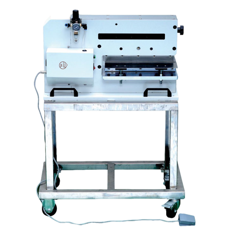
For a straight scored panel, compare the actual roller or guillotine product page. The JLO-C320 page gives a component-to-V-cut-groove distance field, while JLO-C400/C600 has its own applicable-board and operating constraints. Keep those limits attached to the correct product. A clearance value from one separator must not be assigned to another.
3. Check material, thickness and component arrangement
Use the material stack and board thickness from project documentation. Then compare them with each candidate’s published scope. JELIO’s milling-cutter router page lists its cuttable PCBA thickness as a separate field. JLO-C320 gives its own depaneling-thickness range, and JLO-CL3030 UV laser has a different thickness field and panel envelope.
A product category does not establish that every substrate or populated assembly is suitable. Describe copper distribution, components close to the path and any surface condition relevant to your application. These details help the technical team choose the sample setup and the edge locations that need inspection.
The LPKF laser-technology overview describes a different removal mechanism using a focused beam and extraction. This provides process context for the laser option. The selected JELIO laser must still be evaluated using its own product data and an application-specific sample, without importing another manufacturer’s performance statements.
| Question | What to inspect | Next review |
|---|---|---|
| What is the separation path? | Tabs, contours or scored straight lines | Select relevant cutting mechanisms |
| What can obstruct the tool or blade? | Top/bottom components and support areas | Review model-specific clearance |
| What material will be processed? | Documented stack and thickness | Check source product scope |
| What output is required? | Board orientation, tray and next operation | Define handling and receiving |
| What constitutes acceptance? | Drawing limits and edge locations | Agree the sample-review method |
4. Consider integrated cutting when the panel needs both tools
An integrated router-and-saw system offers more than one cutting tool, but each tool still has its own geometry and access requirements. The JLO-CXJ3235 / JLO-CXJ4550 page lists contour functions for the milling cutter and straight-line cutting for the saw. Map the required panel segments to those functions before assuming the whole panel can be processed with one tool.
Review support between the two operations and the condition of already-separated boards. The fixture and path sequence should remain understandable to the process and quality teams. Record the selected milling and saw configuration in the trial so the quotation can describe the same setup.
ASYS’s milling and sawing overview also presents the two processes as part of an equipment configuration discussion. The useful lesson for a buyer is to compare the complete application. It is not a basis for assigning ASYS options or numerical performance to a JELIO integrated machine.
5. Compare the finished board and the complete operating task
Define the sample checks before comparing cycle time. Identify the edge locations, drawing dimensions and handling observations needed for your product. A short demonstration of one cut may leave the rest of the panel, pickup and output sequence unreviewed. Keep the configuration and sample IDs with the inspection record.
For dimensional review, distinguish the catalog’s Cutting Accuracy and Repeatability fields. The metrology-focused guide explains how to keep those questions separate. Neither field is a measurement already made on your drawing characteristic, and a process name does not replace the actual sample evidence.
Record the complete operating task using the same timing boundary for each alternative. Include loading, positioning, separation and receiving as agreed for the comparison. A manually collected board and an automatically delivered board should not be described as the same output scope simply because both machines have finished cutting.
When maintenance or consumables affect the decision, list the actual cutter, blade and support requirements with the proposed service scope. Ask for a configuration-based quotation. This guide supplies no universal cheapest-method ranking, tool-life promise or payback calculation; those decisions require the real panel, operating pattern and commercial proposal.
6. Use a representative trial to finish the selection
JELIO’s technical-support service offers sample cutting, process video, microscope edge analysis, dimensional verification and a machine recommendation report. Prepare the drawing and populated panels with the acceptance questions that distinguish the shortlisted processes. This makes the trial answer a purchasing question rather than producing another generic demonstration.
Ask the team to identify the recommended model, fixture and selected options for each viable route. Keep unsuccessful or revised trial conditions in the record as well, with the reason for the change. A reviewable selection can explain why an alternative remained on the shortlist or was removed.
Carry the chosen process and configuration into the equipment specification and RFQ. Include the handling arrangement, inspection requirements and remaining integration actions. A practical method comparison ends with an application-specific proposal that engineering, quality and purchasing can assess together.
Panel geometry narrows the process question
Review milling and related tool access
Review the specific roller or guillotine model
Compare the sample and output requirement
Choose a mechanism for the actual separation path
| Process / JELIO reference | Mechanism and relevant geometry | Application review focus |
|---|---|---|
| Milling-cutter PCB router — JLO-C3532/C5045 | Spindle-based programmed contour cutting | Fixture, component access and source tool range |
| Roller V-cut — JLO-C400/C600 | Upper circular blade and lower straight blade | V-groove layout and applicable-board limits |
| Guillotine — JLO-C320 | Pneumatic straight scored-panel separation | Groove distance, component height and board thickness |
| Integrated router/saw — JLO-CXJ series | Milling contours plus straight saw function | Tool allocation, access and support between operations |
| UV laser — JLO-CL3030 | Non-contact beam-based separation | Source model envelope, material and sample edge result |
Published specifications for the application review
JLO-C320: source catalog values for this product family.
| Parameter | Published value |
|---|---|
| Model | JLO-C320 |
| Depaneling Length | 0-300MM |
| Depaneling Thickness | 1.0-3.0MM |
| Component Height Limit | Component height ≤ 40 mm for upward depaneling; ≤ 15 mm for downward depaneling |
| Distance from Component to V-cut Groove | ≥3MM (customizable) |
| Working Air Pressure | 0.4-0.6Mpa |
From panel drawing to a justified process choice
- 01
Inspect
Map outline, tabs, grooves and components.
- 02
Shortlist
Select the relevant cutting mechanisms.
- 03
Screen
Read the exact model limits and options.
- 04
Trial
Inspect representative samples and full handling.
- 05
Specify
Quote the accepted process and configuration.
Frequently asked questions
Are milling and router depaneling always separate processes?
Read the actual mechanism. JELIO’s PCB Router pages describe spindle-based milling-cutter equipment. Its Router depaneling machine page for JLO-C400/C600 instead describes roller V-cut equipment, so those product groups should be distinguished by model and mechanism.
When should I review a guillotine separator?
Review it for the straight scored-panel application described by the selected product. Compare the real groove layout, board thickness and component clearance with the JLO-C320 catalog fields and sample-review requirements.
Can an integrated router-saw machine route every segment with either tool?
The linked JELIO integrated catalog lists contour functions for the milling cutter and straight-line function for the saw. Map each required separation segment to the appropriate tool and review fixture support and access.
Is UV laser automatically the best option for every thin board?
Compare the actual material, populated layout and required edge condition with the selected model’s own scope. Arrange a representative trial; another manufacturer’s capability or a general technology description is not a sample result for your panel.
How do I make the final method decision?
Use the released drawing to shortlist mechanisms, screen exact product limits, and evaluate representative samples for edge, dimensions and handling. Request a proposal for the same configuration that supported the review.
Related equipment and guides
Compare cutting methods on your panel
Send the panel drawing and assembly requirements to arrange a process-led sample review.
Compare cutting methods on your panel →