

JELIO ENGINEERING INSIGHTS
V-Cut PCB Depaneling: Groove and Board Review
V-cut PCB depaneling requirements start with the board drawing, not just the name of the separator. A scored panel can have suitable overall dimensions while still presenting a difficult groove, a component obstruction or an unsupported final strip. For a process engineer reviewing the JELIO JLO-C400 or JLO-C600, the useful question is whether the actual panel can be located, separated and collected with the intended assembly in place. This guide turns that question into a drawing and sample review. It distinguishes groove geometry from board thickness and connects each cut line to the evidence needed before the production arrangement is approved.
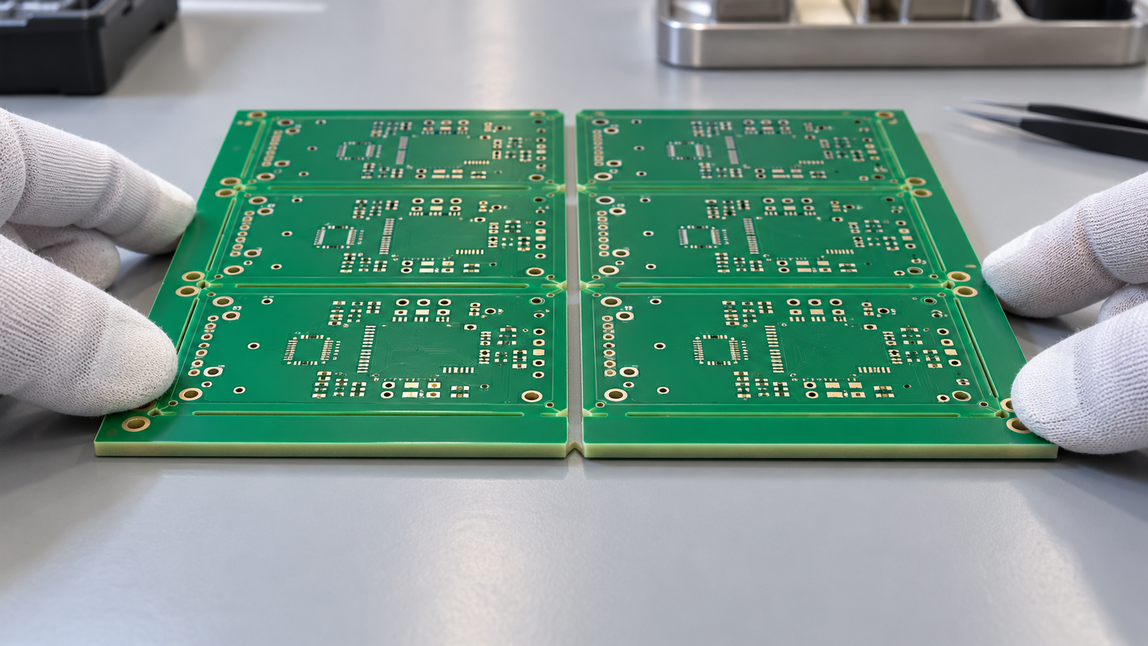
What should you check before choosing V-cut PCB depaneling?
Review the panel drawing, material, overall thickness, groove cross-section and material remaining between opposed grooves. Mark component clearance on both faces, each separation line and the support needed as strips are removed. Compare these details with the selected model’s published requirements, then submit representative samples for a documented trial. Approve the reviewed board revision and handling sequence together.
1. Put groove geometry on the controlled drawing
Start with the panel identifier, drawing revision and material designation. Show scored lines, routed boundaries and the connections remaining after each operation. A plan view alone rarely explains what the blade will encounter. Add a cross-section showing the opposed groove positions, intended residual web and measurement references. Retain the tolerances specified by your board design rather than introducing a process limit in an informal message.
Overall thickness, groove depth and residual web describe different features. Two panels with the same overall thickness can leave different amounts of material at the separation line. A groove dimension alone does not define the remaining material between scored faces. Ask the application engineer which drawing feature the catalog requirement addresses and keep that interpretation beside the section view.
The JLO-C400/C600 Board Depaneling Requirements row is reproduced below exactly from the product data. Do not silently relabel its groove dimension as a residual-web limit. Create a review entry containing the drawing feature, specified value, relevant machine row, supplier interpretation and representative sample. This makes the next question specific enough to resolve.
2. Review the actual material and assembled envelope
Identify the laminate supplied for review, its thickness and any change planned for production. The JLO-C400/C600 Application Scope row names fiberglass board, FR-4 and FR-2 within its stated thickness scope. Use that model-specific information rather than replacing it with a statement about the company’s wider equipment portfolio. A different substrate should remain an explicit application question.
Mark nearby component bodies, leads, connector overhangs and soldered features on both faces. Show their distance from the groove and their relationship to the lower support. Component height is directional: clearing the upper working space does not establish clearance on the other face. Record the board orientation so that top and bottom remain meaningful when photographs are rotated.
Use the existing component-clearance review to prepare the envelope. Add the blade approach and support contact locations for this scored-panel decision. A bare-board drawing cannot represent an assembled connector extending across an edge. Include the intended assembled revision when the production task involves populated boards.
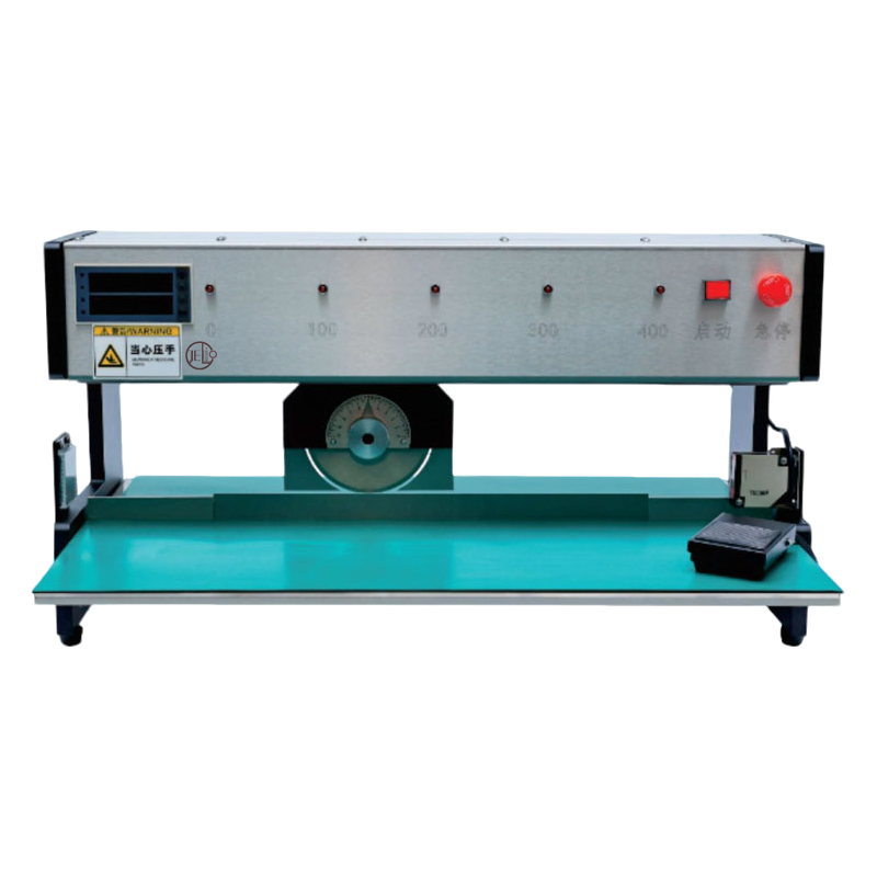
3. Treat each cut line as a separate review item
Create a line register rather than describing the entire panel as suitable or unsuitable. Identify each start and finish, nearby features, interruptions, orientation and the piece remaining after separation. A straight score and a line interrupted by a cutout raise different access questions. Photographs should expose those features rather than show only the panel’s overall appearance.
Review intermediate shapes as well as the finished board. The first operation may leave a broad panel while the last leaves a narrow strip with less support. Define how that strip will be located and collected and whether the board changes orientation between operations. Actual handling must follow the supplied equipment instructions and guard arrangements; the review does not authorize reaching into a working area.
The cab MAESTRO 4X page illustrates why overhangs and groove interruptions warrant manufacturer review. Its blade arrangements belong to that product. For JELIO, submit the marked obstruction and request a response for the selected configuration rather than assuming another manufacturer’s accessory is included.
4. Match model selection with the handling proposal
Keep paired JLO-C400/C600 values in their original model order. Cutter travel, overall dimensions and weight differ across the listed versions. Selecting the largest number from a combined row does not establish that either model provides it. Ask the quotation to identify the exact version and the intended panel orientation, then retain that clarification with the drawing.
The catalog distinguishes manual pickup after separation from a belt-feed upgraded version. If the process proposal depends on a conveyor, record its inclusion and receiving arrangement in the configuration list. A photograph of a belt is not a quotation inclusion. Include a downstream tray or workstation only when it belongs to the agreed supply scope.
The roller separator page is the parameter source; technical support and sample testing is the next step for the workpiece. Send material records, groove sections, assembly views and the cut-line register together. A single revision-controlled package gives the supplier one clear basis for the application response.

5. Close drawing questions with identified samples
Agree what the trial must answer before shipping samples. Identify cut lines, inspection locations, sample labels and checks required by the assembly’s quality plan. Request photographs connecting the full panel, setup and separated edge. Retain configuration and sample identities with the returned material. A clean edge image without a location cannot close a drawing-specific question.
The cab MAESTRO 4S page discusses material-dependent setup and sample boards. The MAESTRO 6 manual distinguishes notch thickness and configuration. Those references support board-specific review; they are not operating settings for a JELIO separator.
Use the sample-test checklist to agree acceptance. Give each registered line a disposition: reviewed configuration, observed condition, unresolved issue and responsible company function. Preserve evidence with the board revision. Changes to laminate, score geometry or the assembled envelope should trigger review of affected lines instead of automatically inheriting an earlier approval.
Three dimensions, three review questions
Screen material and overall section.
Define removed and remaining material.
Check both faces and support access.
V-cut note versus reviewable panel package
| Item | Note only | Reviewable package |
|---|---|---|
| Geometry | Scored line | Section and remaining web |
| Assembly | Bare-board image | Both component envelopes |
| Sequence | Finished outline | Every line and remaining strip |
| Handling | Assumed pickup | Reviewed orientation and collection |
| Release | Visual impression | Sample IDs and dispositions |
Published specifications for the application review
JLO-C400 JLO-C600: source catalog values for this product family.
| Parameter | Published value |
|---|---|
| Model | JLO-C400 JLO-C600 |
| Board Depaneling Requirements | V-groove≥0.2MM, distance between components and groove>1.5MM |
| Cutter Travel | 100MM 200MM 300MM 400MM/300MM 400MM 500MM 600MM |
| Board Cutting Height | Maximum component height on PCBA: less than35mm, Component height on the bottom side: less than22mm |
| Application Scope | Fiberglass board, FR-4, FR-2and other materials with thickness less than3MM |
| Blade Material | Imported SKD11 |
| Working Mode | Jog mode & hold mode |
| Finished PCBA After Depaneling | Manual pickup |
| Upgraded Version | Belt-feed PCB depaneling machine |
Drawing-to-sample review
- 01
Identify
Freeze board and material revisions.
- 02
Map
Define groove section, envelopes and cut lines.
- 03
Screen
Compare model and handling.
- 04
Trial
Inspect identified samples.
- 05
Release
Close line dispositions and revision scope.
Frequently asked questions
Is groove depth the same as residual web?
No. Groove depth describes material removed from a face; residual web describes material remaining between scored faces. Put both on a section view and agree how the requirement maps to the drawing.
Can overall thickness confirm suitability?
It provides an initial screen. Material, groove geometry, assembly envelope, blade access and changing support during separation also need review with representative samples.
Which component dimensions should I send?
Include both face heights, distances to the groove, leads and body overhangs with a defined orientation. Mark support contact locations and connectors crossing the edge.
Is belt feed standard on the roller model?
The catalog distinguishes manual pickup from a belt-feed upgraded version. Ask the quotation to identify the supplied arrangement and review the receiving position.
When should the board be reviewed again?
Review affected lines after changes to laminate, thickness, groove geometry, component envelope, orientation or collection. Retain the earlier evidence so the new review identifies what changed.
Related equipment and guides
Request a scored-panel drawing review
Share groove sections, material records, assembly views and the cut-line register for application review.
Request a scored-panel drawing review →