

JELIO ENGINEERING INSIGHTS
Why Edge Quality Matters More Than Speed in Automotive PCBA Depaneling
Automotive PCBA depaneling decisions need an edge-quality review alongside the production-cycle target. JELIO’s original article explains why a cut that looks acceptable at first glance can still require closer evaluation, especially near sensitive components or critical board features. This expanded guide turns that concern into a practical application-review sequence: define the edge locations, review board support, inspect representative samples and connect the observations to the proposed machine configuration. It is written for quality, process and purchasing teams evaluating a depaneling process for automotive assemblies, including the BMS-board context discussed in the original article.
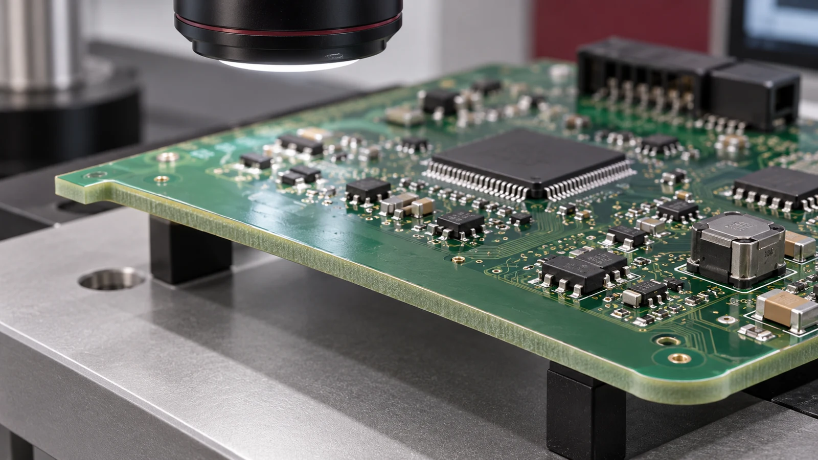
How should automotive PCBA depaneling edge quality be evaluated?
Define the drawing requirements and critical edge locations before cutting. Review the populated board, fixture support and selected process, then inspect identified samples using the agreed edge and dimensional methods. Keep microscope images, measurements and handling observations attached to the same sample and configuration. Evaluate complete-cycle performance after the required quality checks, with any reliability testing defined by the responsible customer or quality team.
1. Identify which edges and components are critical
Start with the released assembly drawing and the finished board outline. Mark edges close to components, connectors, fastening features or locations that influence assembly fit. Identify tab-removal points and corners separately from long straight sections. This gives the sample inspection a defined map instead of relying on a general impression of the board.
The original JELIO article uses a BMS control-board example to explain why latent edge damage matters in automotive electronics. Keep that reliability concern connected to the specific product requirements. The depaneling review should state which observations can be made during the cutting trial and which additional qualification activities belong to the customer’s wider reliability program.
Record the panel revision and board position for every inspected sample. A photograph of one favorable edge does not describe all tab locations or panel positions. Ask the quality team to select representative features and define the inspection method before the trial so the supplier and buyer are reviewing the same characteristic.
2. Review the fixture and the separation sequence
A cutting tool acts on a board that is supported by a fixture or handling arrangement. Review where the populated panel is held, which areas must remain accessible and what happens when each board becomes separated. The state after the final cut matters as much as the state before cutting, because support and receiving conditions can change during the sequence.
Supply component positions and heights on both sides. In the JLO-C3532 / JLO-C5045 catalog, component height is listed as upper 15 mm and lower 45 mm. Use the exact source field as an initial screening value, then review the proposed fixture and tool access for the actual populated layout. Do not treat a catalog envelope as a substitute for the application drawing.
For a sample trial, keep the fixture identification, tool and program revision with the board record. If the team changes support points or the cutting order, retain a separate revision of the trial. The sample-test checklist describes how to carry configuration changes into a reviewable record.
3. Use edge appearance, dimensions and handling as separate checks
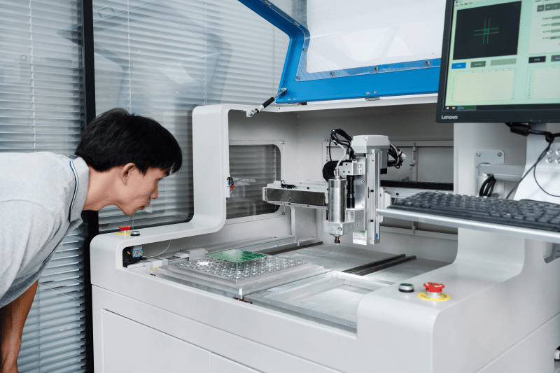
An edge-image record should identify the sample, inspection location and imaging method. Capture an overview that locates the feature and a closer image for the agreed edge observation. Use consistent labeling so the images can be reviewed alongside dimensional records without confusing different boards or cutting conditions.
Dimensional acceptance needs its own characteristic, datum and drawing limit. The router catalog’s Cutting Accuracy and Repeatability fields are not interchangeable. Consult the accuracy versus repeatability guide when writing the request so an equipment specification is not accidentally reported as a measurement already made on your sample.
Record handling observations separately: how the panel is loaded, whether separated boards remain supported and how they reach the receiving position. A quality issue observed after pickup may need a different investigation from an edge condition observed immediately after cutting. Keeping the stages distinct gives the engineering team a more useful starting point.
| Check | Evidence to retain | Requirement owner |
|---|---|---|
| Cut edge | Sample ID, feature location and microscope image | Quality/process team |
| Finished dimensions | Drawing characteristic, datum, reading and method | Quality/metrology team |
| Board support | Fixture revision and cutting sequence | Process engineering |
| Pickup and receiving | Orientation and handling observations | Automation/process team |
| Reliability qualification | Customer-defined method and acceptance record | Customer/responsible quality team |
4. Connect the observation to the actual process configuration
JELIO’s original article describes control of spindle speed, feed and cutting depth as part of its milling approach, and refers to its burr-free depaneling development and patent portfolio. Those company statements remain part of the application context. For a purchasing review, ask which selected setup, tool and program will be used for your own panel.
Record extraction configuration with the trial. The related router page lists bottom full suction, with bottom follow-up and top extraction arrangements optional. Describe the actual quoted arrangement and the inspection location where cleanliness matters. This keeps a discussion about dust collection connected to the populated assembly and receiving process.
Global manufacturer guidance also treats process selection and edge condition together. The LPKF technical-cleanliness explanation discusses cleanliness in its own laser systems. It is useful context for asking about residue and the finished edge, while all JELIO outcome claims and trial conclusions must remain tied to JELIO’s own information and your sample.
5. Evaluate production speed after defining quality acceptance
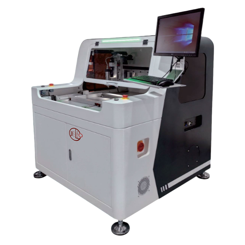
Write the acceptance checks before the timing target. Then observe the complete sequence using the same panel and configuration that produced the inspection evidence. Define whether loading, positioning, cutting, unloading and receiving are included. A short cutting-path video cannot, by itself, establish the complete production cycle.
If a program or fixture changes to address a quality observation, review the timing again for that revised setup. Likewise, if the line review changes pickup or receiving, keep the quality and handling records connected. This avoids approving an attractive timing result from one configuration while relying on edge evidence produced by another.
The inline versus offline guide helps frame the wider automation decision. Both workflows still need sample quality acceptance. Choose the handling arrangement that fits your product mix and required sequence, then document the specific configuration your team intends to purchase.
Do not create a universal strain limit, defect rate or reliability claim from a qualitative trial observation. If the customer requires additional strain or environmental qualification, identify the responsible test method and reviewer in the project plan. Retain the actual results when they are available rather than substituting a generic depaneling benefit.
6. Carry the quality record into equipment acceptance
Send the drawing, critical-edge map and representative populated panels to JELIO technical support. The service page lists sample cutting, complete-process video, microscope edge analysis, dimensional verification and a machine recommendation report. Specify which deliverable should resolve each open application question.
At review, retain an explicit disposition for each required check: accepted, corrective action or further evidence requested. Name the sample and trial revision behind that decision. The RFQ should reference the accepted fixture, tool-change and extraction configuration so purchasing can compare the proposal with the evaluated setup.
Use the resulting record during the later equipment handover as well. Sample qualification, factory acceptance and site acceptance can share feature definitions, but each should identify its own configuration and conditions. The practical objective is a consistent quality requirement across the purchase process, with production speed evaluated inside that requirement.
Three observations that should stay connected
Inspect the separation result
Check the released drawing
Review the whole board sequence
A speed-only review vs. a quality-led production review
| Review point | Speed-only emphasis | Quality-led review |
|---|---|---|
| Starting requirement | Shortest observed cutting segment | Drawing and critical-edge criteria |
| Configuration | Often summarized as a machine name | Fixture, tool, program, support and extraction |
| Evidence | Selected process footage | Identified edge images, dimensions and handling record |
| Timing | Cutting time alone | Complete cycle for the accepted configuration |
| Purchase decision | Headline throughput | Quality disposition with the actual production sequence |
Published specifications for the application review
JLO-C3532/JLO-C5045: source catalog values for this product family.
| Parameter | Published value |
|---|---|
| Model | JLO-C3532/JLO-C5045 |
| PCBA Component Height | Upper:15mm Lower:45mm |
| Cuttable PCBA Thickness | 0.5~4mm |
| Spindle Tool Range | φ0.5~3mm |
| Cutting Accuracy | ±0.05mm |
| Repeatability | ±0.02mm |
| Dust Collection Method | Bottom full suction, bottom follow-up dust collection (optional), top dust collection (optional) |
A quality-led automotive depaneling review
- 01
Define
Identify critical edges and project criteria.
- 02
Configure
Review fixture, tooling and extraction.
- 03
Trial
Record identified populated samples.
- 04
Inspect
Review edge, dimensions and handling.
- 05
Accept
Approve the same configuration and timing scope.
Frequently asked questions
Can a visually clean edge establish automotive reliability?
Visual edge review is one part of the application record. Any required reliability or strain qualification should use the customer-defined method and acceptance requirement, with actual results retained by the responsible quality team.
Which edge locations should be reviewed in a sample trial?
Use the released drawing to identify tab-removal points, corners, component-adjacent edges and features that influence assembly fit. Keep sample ID, panel position and inspection location attached to each observation.
Why should fixture revision be recorded?
Board support and the separation sequence are part of the evaluated setup. If support points, cutting order or receiving conditions change, the inspection and timing evidence should identify the revised configuration.
How does JELIO support an edge-quality review?
Its technical-support page lists free sample cutting, process video, microscope edge analysis, dimensional verification and a machine recommendation report. Provide the panel and the specific checks your application requires.
Should cycle time be measured before or after a quality adjustment?
Review the complete cycle for the configuration that meets the agreed quality checks. If the fixture, path or handling changes, retain a revised record so timing and quality refer to the same setup.
Related equipment and guides
Request an automotive panel edge review
Send the populated-panel layout, critical-edge locations and drawing criteria to the JELIO engineering team.
Request an automotive panel edge review →