
 WhatsApp: +8615306204105
 Email: 516947921@qq.com
JELIO ENGINEERING INSIGHTS
UV Laser Depaneling: Qualifying a Sample Panel
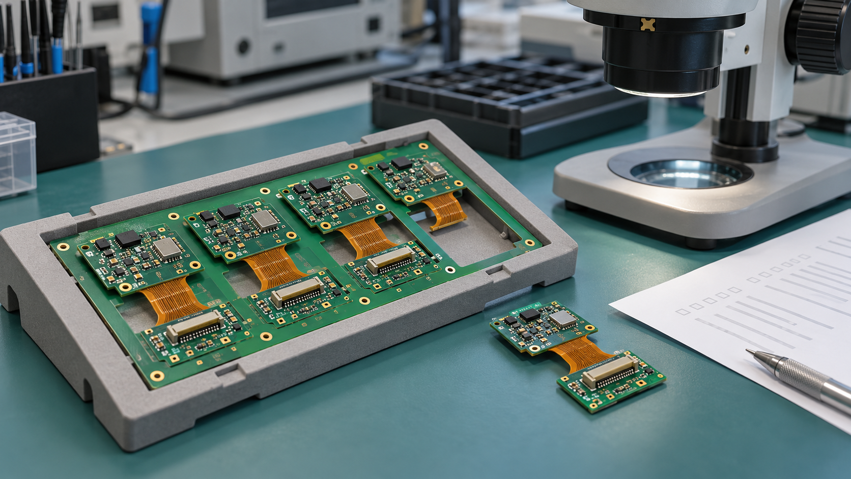
UV laser depaneling sample qualification should explain why a particular panel, material and machine configuration are suitable for the intended assembly. A photograph of a separated board is useful, but a purchase decision also needs the drawing revision, cut-edge observations, dimensional checks and conditions under which the sample was produced. This guide helps quality engineers prepare that evidence for the JELIO JLO-CL3030. It focuses on UV-specific review points such as the cut wall, local heat effects, alignment, support and extraction, then organizes them into a release record. Use it with the general sample-test checklist when defining what JELIO should return after a trial.
How do you qualify a UV laser depaneling sample?
Identify the actual laminate, layer stack, panel and assembly revisions, then agree on inspection locations and acceptance criteria before cutting. Record the supplied laser configuration, alignment, support, extraction and program used. Review the cut wall, nearby features and specified dimensions on identified samples. Retain observations and any additional tests required by your quality plan, then approve the documented configuration and covered revisions.
1. Make the sample represent the assembly you will buy for
Assign a sample ID to each panel and connect it to the laminate designation, layer stack, thickness information, panel drawing and assembly revision. Identify whether it is bare, partly populated or representative of the intended production assembly. For rigid-flex designs, mark the rigid and flexible regions and the layers present where separation will occur. Keep any material substitutions visible in the report.
Provide the intended cut contour and identify copper, coverlay or other layers that the path intersects. Add top and bottom assembly information near sensitive locations. These details give the application engineer a specific workpiece to evaluate. If only a simplified coupon is available for an initial discussion, state the follow-up assembly that must be reviewed before the purchase decision is released.
Use the existing sample-test acceptance checklist for the overall trial agreement. This UV-focused record adds the cut-wall, local heat-effect and extraction questions. Agree who supplies the representative material and who approves the inspection criteria, so the returned sample can answer a defined quality question rather than serve only as a demonstration piece.
2. Screen the JLO-CL3030 configuration without mixing parameters
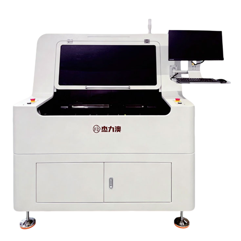
Read the JLO-CL3030 product specification against the submitted panel. Its cuttable PCB thickness row states <1.5mm, and its maximum depaneling size is 300mm (X) * 300mm (Y). Keep the inequality and the full panel envelope in the review. The final individual-board size alone does not describe the handling frame and loaded workpiece.
The catalog separates cutting accuracy, repeat positioning accuracy and axis movement resolution. Identify which value addresses each purchasing requirement rather than treating them as interchangeable. Use the accuracy and repeatability guide for the terminology, while retaining the laser model’s own source values. Actual sample measurements need their own datum, method and recorded result.
The same specification lists a 20W maximum laser output row and a separate Laser Source row with 20W / 30W / 60W Optional. Preserve both source statements and have the proposal name the configuration supplied for the trial and order. Also identify whether optional vacuum adsorption is included. A trial report should describe the equipment used instead of combining different listed configurations into one assumed setup.
3. Define what will be examined on the cut wall
Mark inspection locations before the panel is separated. Include entry and exit regions, changes in contour, local material transitions and features near the cut that matter to the assembly. Agree on the viewing method and how images will be identified. Keep cut-wall appearance, visible edge damage and retained debris as separate observations rather than giving the entire panel one unexplained visual pass.
An IPC-hosted technical paper on laser cut quality examines cut-wall condition and electrical effects in its stated experiments. It supports asking which evidence is appropriate to the end application. Its experimental results are not JELIO sample results. Where your quality plan calls for electrical or material testing, agree the method, responsible laboratory and report before treating the sample as released.
The JELIO product performance section describes a heat-affected zone of about 0.1mm. Keep this published statement attached to JLO-CL3030, then define the actual locations and observations requested for your sample. If the acceptance question concerns an internal material change, agree a suitable examination method; an ordinary photograph should be recorded for what it shows, with the relevant follow-up inspection identified.
4. Link dimensional checks to alignment and board support
Choose the inspection datum and the dimensions to report from the released drawing. Identify which edge belongs to the finished board, which part is waste and how the sample is oriented during inspection. Retain the measurement method and sample ID with each result. This makes the dimensional record useful to a quality engineer who did not attend the demonstration.
Record the alignment references used in the trial and retain an image or program reference that identifies them. JLO-CL3030 lists automatic camera alignment. The application review still needs to connect the chosen references to the panel drawing and the intended cutting contour. If the panel revision changes a fiducial, handling rail or local contour, review the associated program rather than carrying forward a previous approval unchanged.
Describe support before, during and after separation, particularly for flexible regions and small detached boards. Identify the supplied support arrangement and any vacuum adsorption option used. Ask how the final board and waste remain controlled and are removed. The fixture design review provides related support questions; the laser sample record should describe its own actual support arrangement.
5. Record extraction and inspection conditions together
The laser product page lists bottom-following suction as standard. Record the extraction arrangement used during the sample and the condition in which the boards are presented for inspection. Note any cleaning, wiping or other handling between cutting and photography. This helps reviewers distinguish the observed process output from a sample prepared differently before its final photograph.
LPKF’s technical-cleanliness discussion treats cut-edge condition as a process-specific issue. Use that context to define your own inspection questions; proprietary process claims remain with their source. Ask which accessible surfaces and component-sensitive areas will be examined and how the observations will be documented for the JELIO trial.
JELIO technical support offers complete-process video, microscope edge images and dimensional verification as part of sample testing. Specify the requested views and sample IDs in advance. If a different test or inspection report is needed for your product, agree its scope and provider separately so the returned package contains evidence your quality team can actually use.
6. Release a sample record with clear revision coverage
Create a single index linking the drawing package, configuration, cutting program, video, inspection images and measurement record. Give every finding a location and a disposition. An accepted area and an open question can coexist in the same trial report; assign the follow-up to a named company function and define which evidence will close it before purchase acceptance.
For a repeat trial, record what changed and which earlier evidence is still applicable. A revised laser setup, support arrangement or material should have an identifiable revision, with the affected inspections repeated according to the agreed plan. Keep the original and repeat records linked. This provides a reviewable qualification history rather than a sequence of unrelated “good sample” photographs.
Finish by listing the panel and assembly revisions, supplied configuration and acceptance documents covered by the approval. Record what triggers a further review and who controls the production program. To prepare a comparable router or laser proposal from the same starting information, use the companion drawing-data checklist.
| Review item | Evidence to attach | Release question |
|---|---|---|
| Material identity | Laminate, layer stack, thickness and sample IDs | Does the sample represent the intended assembly? |
| Cut-wall locations | Annotated contour and identified microscope views | Are the agreed edge observations addressed? |
| Local sensitive features | Relevant component and conductor locations, agreed test reports | Are product-specific follow-up checks complete? |
| Dimensions and alignment | Datum, drawing requirements, measurement method and results | Can each result be traced to a requirement? |
| Support and extraction | Supplied setup, options, process video and cleaning record | Can the reviewed sample conditions be reproduced? |
| Disposition | Findings, changes, responsible functions and approval coverage | What is released, and what remains an open action? |
Visual review: three different pieces of qualification evidence
Read the model envelope, source parameters and supplied options.
Connect cut-wall images and dimensions to the actual setup.
Identify covered revisions, retained records and follow-up actions.
Initial trial versus released UV laser sample process
| Decision area | Initial cutting trial | Released sample process |
|---|---|---|
| Workpiece | Record the supplied panel and any simplified features | Identify the approved material and assembly revisions |
| Machine setup | Record the configuration used for the demonstration | Name the supplied options and controlled setup |
| Edge evidence | Capture observations at identified locations | Close agreed edge and product-specific inspection actions |
| Dimensional evidence | Retain sample measurements with a stated method | Link results and dispositions to released drawing requirements |
| Changes | List adjustments made during the trial | Define revision coverage and review triggers |
| Purchase decision | Identify evidence still needed | Approve the documented scope and remaining responsibilities |
Published specifications for the application review
JLO-CL3030: source catalog values for this product family.
| Parameter | Published value |
|---|---|
| Model | JLO-CL3030 |
| Max. Depaneling Size | 300mm (X) * 300mm (Y) |
| Cuttable PCB Thickness | <1.5mm |
| Cutting Accuracy | ±20μm |
| Laser Wavelength | 355nm, Diode-Pumped Solid-State Laser (DPSS Laser) |
| Max. Laser Output Power | 20W |
| Laser Source | 20W / 30W / 60W Optional |
| Positioning Method | Automatic Camera Alignment |
| Flexible PCB Adsorption Method | Vacuum Adsorption (Optional) |
| Dust Extraction Method | Bottom-Following Suction (Standard) |
UV laser sample qualification workflow
- 01
Identify the panel
Freeze material, layers, drawing and assembly revisions.
- 02
Agree the checks
Mark inspection locations, requirements and responsible functions.
- 03
Cut and record
Retain the actual laser configuration, support, extraction and program.
- 04
Review and repeat
Inspect the identified samples and document any controlled changes.
- 05
Release the scope
Approve the evidence index, covered revisions and follow-up responsibilities.
Frequently asked questions
Can a bare coupon qualify a populated UV laser depaneling application?
A coupon can support an initial material discussion. Identify the features it represents and the assembly details still to review. Purchase acceptance should address the agreed production-representative panel, support, nearby features and required inspection evidence.
Does a clean-looking edge establish every quality requirement?
It addresses the visible condition under the stated inspection method. Define dimensional and product-specific electrical or material requirements separately and agree the relevant reports. Attach observations to identified locations and samples so each approval answers a specific requirement.
Which JLO-CL3030 power value should the sample report record?
Name the configuration actually supplied for the trial. The catalog has a Max. Laser Output Power row stating 20W and a separate Laser Source row listing 20W / 30W / 60W Optional. Keep those source rows distinct in the application and quotation review.
What happens if the panel material or revision changes after the trial?
Identify the change and review the affected cutting program, support, alignment and inspection requirements. Link any repeat trial to the original sample record and define which evidence remains applicable before extending approval to the revised assembly.
What should I request from JELIO after sample cutting?
Request the agreed process video, identified microscope edge views, dimensional verification and machine recommendation together with the panel revision and supplied configuration. List any additional product-specific tests and responsible providers in the trial agreement.
Related equipment and guides
Request a UV laser sample qualification review
Send your material and layer information, panel and assembly drawings, representative samples and quality requirements so JELIO can agree the trial and evidence package with you.
Request a UV laser sample qualification review →


