
 WhatsApp: +8615306204105
 Email: 516947921@qq.com
JELIO ENGINEERING INSIGHTS
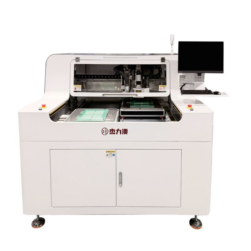
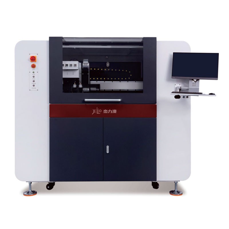
Integrated Router and Saw: Planning Mixed Toolpaths
A router and saw integrated PCB toolpath needs more than a list of lines and curves. The process engineer must establish which cuts have access, what remains supported after each operation and how the two methods meet at the finished edge. This guide uses the JELIO integrated router and saw listing to frame a review of mixed cutting operations. It explains how to send a cut register that a fixture designer can evaluate and how to record the evidence needed to release a specific panel revision.
How should a mixed router and saw path be planned?
Assign each cut to a proposed tool and mark the shared junctions. Check the swept space around the blade and cutter, then draw the support remaining after each operation. Review the reference marks at transitions and agree how to inspect the junction on identified samples before releasing the program.
Draw the operations on the panel
Start with the fabrication outline and the populated assembly at the same revision. Assign a cut identifier to every separation segment, including a straight segment that ends next to an arc. The identifier should survive export to the supplier and appear on the returned sample record. Mark each line as a saw candidate, a milling candidate or an unresolved transition. A candidate is a request to review access, not a released machine instruction.
A saw candidate needs room for the blade to enter and leave. A line may look straight in a drawing while a nearby connector, clamp or retained rail occupies the blade's swept space. Ask for that space to be drawn over the populated panel and fixture. For a milled contour, review the cutter approach, the corner geometry and the surface the fixture will support. Evaluate the endpoint shared by the two methods separately; an acceptable saw segment and an acceptable arc do not automatically make an acceptable junction.
Plan the support after every cut
Draw the panel as it looks after each operation. A rail that locates the incoming assembly can cease to locate the remaining piece after the first separation. Likewise, a tab used to hold a board during milling may be unavailable if a proposed saw path removes it first. Label the features used as datums, clamps and temporary supports, and identify the operation after which each feature disappears. This gives the fixture designer enough information to challenge the order before making a fixture.
Do not prescribe saw-first or router-first for every panel. Instead, compare the two sequences against the location and support they leave for the next cut. For a small board near a perimeter rail, check who or what retains the board as its last connection is removed and how it is collected. If the next tool has to approach a newly free edge, ask how the board is held during that approach. Keep the offcut in the drawing too: it needs a place to go without obstructing the next movement.
Check the change of tool and coordinate reference
The integrated router and saw catalog lists straight cuts for the saw and straight and shaped contours for milling. It distinguishes manual milling cutter replacement from the optional automatic arrangement. Confirm the quoted configuration before asking for a trial sequence; a replacement method does not by itself describe when the programmed process changes between the two cutting operations.
For each transition, record the last verified datum, the fixture state and the first path on the next tool. Include the location of reference marks and any features that disappear after separation. Automatic camera compensation is listed in the catalog, but the drawing review still needs to identify what the process is expected to reference at each stage. Ask the supplier to show the first cut after the transition on the same drawing revision used for the initial alignment. Keep that check separate from a tool replacement check.
Turn the drawing into a reviewable trial
Send the supplier the original panel drawing, the populated assembly views, the cut register and the proposed sequence. Ask for a marked return drawing identifying paths accepted for review, changes requested and open questions. When a route is unresolved, give the trial a defined decision: for example, whether the residual material at the junction can be removed without moving the finished edge outside its drawing tolerance. Treat the example as an acceptance question, not an assertion about a result.
Choose samples that represent the assembly features most likely to restrict access. Keep the part numbers and revisions visible on the sample record. Identify edges cut by each method and record the joint between them independently. Note which face was inspected and how the edge was measured. A photo showing a clean long straight edge does not document what happened where the blade stopped or the cutter entered.

Release a mixed recipe with revision limits
Before approval, separate dimensional acceptance, edge appearance and successful handling into distinct checks. State what happens when only one check fails: a handling problem may call for a new fixture while an edge geometry problem may call for a revised path. Do not bury those differences in a single pass box. Return the marked drawing with the sample identifiers so another engineer can reconstruct what was run and which cuts were actually inspected.
Make the released record identify the selected tools, fixture revision, panel revision and sequence. List the changes that require a new review, such as a relocated connector, altered rail or changed contour. For a purchase handoff, send the same package to the team comparing station and panel envelopes. That comparison answers whether the candidate configuration can accommodate the assembly; the cut register answers what the process must do once it is inside.
Example: a straight cut that meets a milled corner
Suppose a panel drawing has a long straight separation line that stops beside a rounded corner. Put the junction on the review drawing at a scale that makes the approach visible. If the blade needs to pass the intended endpoint to complete the straight cut, mark that region as unresolved rather than extending the nominal finished outline. Ask whether milling a short portion of the straight segment would move the transition away from the obstructed area. The supplier can then assess both alternatives using the same board and fixture constraints.
Keep each proposed change separate in the trial record. If the trial changes both the transition location and the order of operations, record both changes so the accepted recipe is reproducible. Review the application package with JELIO technical support before treating any trial suggestion as a production instruction.
Two tools, one finished edge
Check cutter access and finish
Review tool approach and corner
Check entry and finished edge
Saw and milling review by cut
| Operation | Saw review | Milling review |
|---|---|---|
| Straight segment | Check blade swept space | Check cutter access and finish |
| Shaped contour | Keep outside straight saw candidate | Review tool approach and corner |
| Junction | Check the stop region | Check entry and finished edge |
| Support | Identify retained datum | Confirm support after prior cut |
Published specifications for the application review
JLO-CXJ3235/JLO-CXJ4550: source catalog values for this product family.
| Parameter | Published value |
|---|---|
| Model | JLO-CXJ3235/JLO-CXJ4550 |
| Milling Cutter Cutting Function | Straight line, L-shape, U-shape, circle, arc, etc |
| Saw Blade Cutting Function | Straight line |
| Milling Cutter Tool Range | φ0.5~3mm |
| Saw Blade Tool Range | Saw blade thickness:0.3mm; diameter:100mm |
| Milling Cutter Replacement Method | Manual tool change / Automatic tool change (optional) |
| Saw Blade Replacement Method | Manual blade change |
| Mark Compensation | Camera recognition & positioning, automatic compensation |
Cut register to recipe release
- 01
Map
Assign each cut an identifier.
- 02
Check
Draw swept space and support.
- 03
Trial
Inspect identified junctions.
- 04
Release
Record the recipe and revision.
Frequently asked questions
Can both tools make straight cuts?
The linked catalog lists straight cuts for both. Choose candidates by access, support and the finished-edge requirement.
Should the saw always go first?
No. Choose the order after reviewing the datums, supports and offcuts left by each proposed operation.
What should a junction trial inspect?
Identify the junction on the drawing and inspect edge position and residual material there, separately from the long straight edge.
Is automatic milling cutter replacement standard on the paired listing?
The paired listing gives manual replacement and identifies automatic tool change as optional.
What should I submit for review?
Send the revision-controlled assembly views, cut register, fixture assumptions and representative samples.
Related equipment and guides
Request mixed-toolpath review
Send the cut register, assembly drawing and sequence for technical review.
Request mixed-toolpath review →


