

JELIO ENGINEERING INSIGHTS
Router or UV Laser: Drawing Data to Prepare
A PCB router laser drawing checklist should let two application reviews start from the same workpiece and the same acceptance requirements. Sending an outline to one supplier and a fully populated panel package to another produces proposals that are difficult to compare. This guide helps process engineers assemble a controlled set of panel, material, component and inspection data before evaluating routing or UV laser depaneling. It uses the JELIO JLO-C3532 / JLO-C5045 router family and JLO-CL3030 laser catalog as specific references. The result is a shared file manifest with process-specific overlays, so differences in a proposal can be traced to a defined engineering decision.
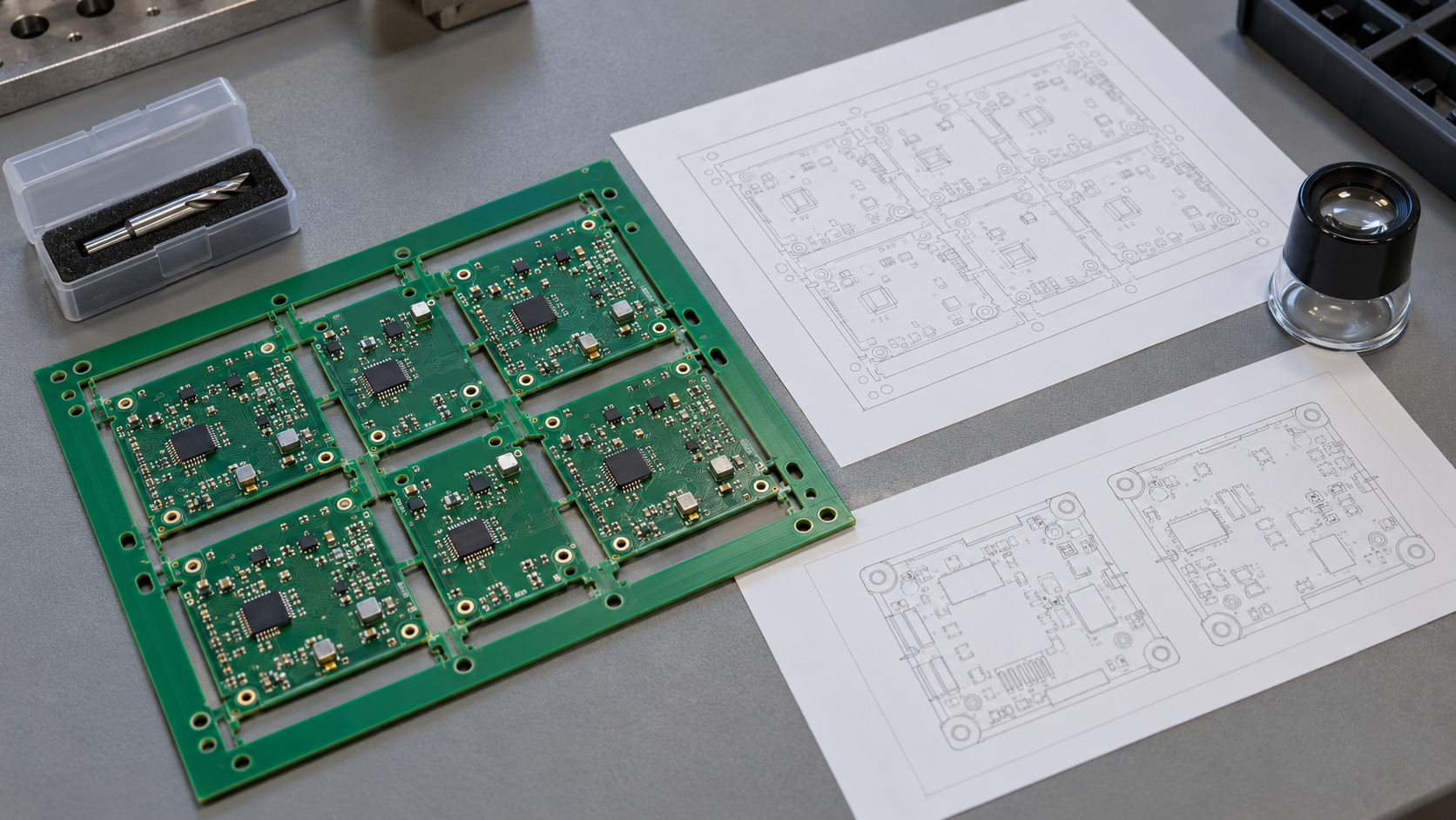
What drawing data should you prepare for router or UV laser depaneling?
Prepare the released panel and finished-board outlines, material and layer stack, thickness, tabs, datums, fiducials and top/bottom assembly geometry. Identify protected areas, support contacts, output handling and acceptance dimensions. Add a router tool-access overlay or laser cut-layer and local-feature review as appropriate. Issue the files with units, orientation and revisions in one manifest, then request a proposal against that same controlled package.
1. Issue a manifest before comparing two processes
List every file with its document purpose, revision, units, orientation and approval status. Identify the master panel drawing and the finished-board drawing, then connect them to the same assembly revision. State the coordinate origin and the viewing convention for bottom-side data. If two files disagree, identify which source controls the feature and resolve the conflict before programming or quoting tooling.
Keep design authority separate from proposal markup. The product team owns the released board geometry and protected features; an equipment supplier may propose a cutting path or support arrangement for review. Store that proposal as an overlay with its own revision instead of silently replacing the design outline. This makes subsequent discussions traceable when the preferred process or fixture concept changes.
LPKF’s panel-design guidance discusses the connection between panel structure and separation method. The practical deliverable here is a common input package for a JELIO application review. Keep supplier-specific design allowances with their source and request a review of your actual panel rather than applying a generic spacing value to every process.
| File or record | Minimum identification | Reviewer question |
|---|---|---|
| Master panel and board outline | Part, revision, units, origin and finished/waste boundaries | Which geometry controls the proposed cut? |
| Material and layer stack | Laminate, thickness information and layer identification | What materials and layers intersect the path? |
| Assembly information | Top/bottom views, heights, overhangs and protected areas | Can the proposed process and support access the panel? |
| Process overlay | Candidate method, path, support and alignment references | Which items are proposals awaiting approval? |
| Acceptance and output | Datums, required dimensions, inspection and board destination | What constitutes an acceptable completed process? |
2. Distinguish the finished contour from panel preparation
Identify the finished board edge separately from pre-routed slots, connecting tabs and handling rails. Mark which segments require separation and which are already open. Include internal cutouts and waste pieces that could become loose during the sequence. An outline drawing without these distinctions can leave the supplier comparing a full-perimeter cut with tab removal without realizing the work scope has changed.
Record the complete panel envelope, including rails and features used for handling. Then identify the individual-board envelope and intended output orientation. Check the full loaded workpiece against each candidate model. A finished board may fit a machine while the surrounding panel or the proposed support and handling arrangement requires a different review.
Keep dimension requirements tied to the finished feature and its datum. If an outline is exported from another design system, review units, arcs, closed boundaries and orientation after export with the application engineer. Record any repaired or clarified geometry in the manifest. Do not approve a machine program only because its preview resembles a screenshot of the intended panel.
3. Add the material stack and both assembly faces
Supply the actual laminate designation and thickness information, and identify relevant copper and other layers at the cutting boundary. For flexible or mixed constructions, distinguish the regions on the panel map. A top-view drawing cannot describe an internal material change or a layer that continues across an apparent visual boundary. Make those intersections part of the application review.
Add component heights, connector overhangs, bottom-side features and product-specific protected areas. Identify permitted support contacts and regions that should remain accessible for extraction or handling. Use the component-clearance guide for the local interference register. Keep its decisions linked to the same assembly revision as the drawing package.
Give each concern a location and a responsible reviewer. A note such as “keep clear of components” is difficult to act on without the component outline and relevant geometry. Where information is still being prepared, identify the specific missing file or feature and the decision it blocks. This keeps the quotation discussion focused on an actionable engineering question.
4. Prepare a router tool-and-support overlay
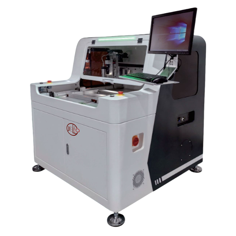
For routing, ask for the selected cutter and the complete moving assembly to be reviewed against the panel. Distinguish the intended finished contour from the cutter centerline, and check approach, entry, travel between segments and exit. Include the holder, clamps and local extraction hardware in the access discussion. A centerline that avoids a component does not describe the full moving envelope.
The JLO-C3532 / JLO-C5045 catalog provides the machine tool range, component-height envelope and cutting functions. Keep those model values attached to the router proposal. Use the cutter-selection worksheet to identify the orderable tool and approved path assumptions, and the fixture design guide to review support through the cut sequence.
Do not assume that a data format listed for the laser model is automatically supported by the router workflow. Ask how the supplied design data will be converted, reviewed and controlled for the quoted router setup. Record the resulting program identifier and revision, including who approves any geometry clarification before a representative panel is cut.
5. Prepare a laser contour-and-layer overlay
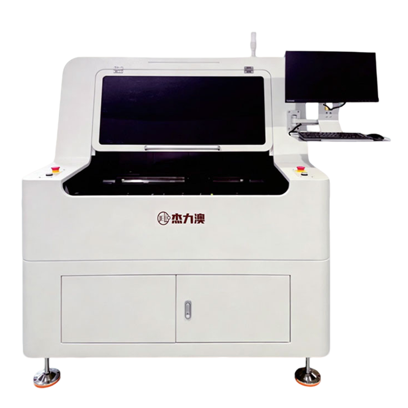
For the laser review, identify the intended cut contour together with the materials and layers intersected by each relevant segment. Mark nearby component and conductor features, alignment references and regions where support may influence access. Ask the application engineer to review the cutting strategy against this annotated workpiece. A lack of a physical router bit does not remove the need to define the assembly and support geometry.
The JLO-CL3030 specification lists Gerber and DXF as supported data formats, alongside automatic camera alignment. Provide the suitable files with their layer meanings, units and revision context. A DXF contour and a stack description answer different questions; an importable outline should be accompanied by the assembly and material information needed for the review.
Define the local edge and inspection questions before selecting a sample plan. The companion UV laser qualification guide covers cut-wall observations, dimensional evidence and the supplied configuration. Link those requirements to the drawing locations so the laser proposal and the later sample report refer to the same acceptance package.
6. Close the review with comparable scope and a sample decision
Give each candidate proposal the same input manifest and ask it to list the included configuration, tooling or support, program preparation, handling and trial deliverables. Highlight any proposed panel revision or additional preparation. A useful comparison shows what each offer includes for the agreed workpiece, rather than ranking two nominal machine names that cover different tasks.
ASYS’s depaneling overview presents equipment alongside handling and configuration choices. Use that broader application perspective when writing the quotation request; none of its parameters become JELIO specifications. Include loading, separated-board removal and waste handling in the drawing review so the end condition is defined as clearly as the cut contour.
JELIO technical support offers free sample cutting, process video, microscope edge images and dimensional verification. Submit the agreed package with representative samples and an evidence request. After the trial, link the approved proposal overlay, program and sample findings to the manifest, then record the revisions covered by the purchase decision and any remaining actions.
Visual comparison: shared input, different review overlays
Panel, stack, assembly, datums and acceptance requirements.
Cutter assembly, compensated path, entry and fixture contacts.
Cut-layer intersections, alignment, support and inspection locations.
Router and UV laser drawing reviews: what each overlay must answer
| Input | Router review | UV laser review |
|---|---|---|
| Finished contour | How does the selected cutter and compensated path produce it? | How is the intended contour related to the processed layers? |
| Nearby features | Does the complete tool, holder and fixture envelope clear them? | Are local component, conductor and support features included in review? |
| Material and thickness | Is the actual stack suitable for the proposed tool and setup? | Is the actual stack suitable for the proposed laser configuration? |
| Support and output | What holds each board through tab removal and unloading? | What supports each board through separation and unloading? |
| Data handover | Agree the router programming and geometry-approval workflow | Provide supported files with units, layer meanings and revisions |
| Acceptance | Link edge and dimensional checks to drawing requirements | Link cut-wall, local-feature and dimensional checks to requirements |
Published specifications for the application review
JLO-CL3030: source catalog values for this product family.
| Parameter | Published value |
|---|---|
| Model | JLO-CL3030 |
| Supported Data Formats | Gerber, DXF |
| Max. Depaneling Size | 300mm (X) * 300mm (Y) |
| Cuttable PCB Thickness | <1.5mm |
| Cutting Accuracy | ±20μm |
| Positioning Method | Automatic Camera Alignment |
| Flexible PCB Adsorption Method | Vacuum Adsorption (Optional) |
| Dust Extraction Method | Bottom-Following Suction (Standard) |
| MES Integration | MES Captured CSV Text Format (Standard), Barcode Scanner (Optional) |
Drawing-package workflow for a comparable application review
- 01
Freeze common inputs
Issue the panel, stack, assembly and acceptance manifest.
- 02
Add process overlays
Prepare distinct router-access and laser-layer review questions.
- 03
Resolve geometry and scope
Agree controlling documents, proposed changes and supplied configuration.
- 04
Run representative samples
Connect process video and inspections to drawing locations and revisions.
- 05
Release the package
Link approved files, programs, evidence and quotation responsibilities.
Frequently asked questions
Is a DXF outline enough for a populated-board application review?
It can describe contour geometry, but the review also needs material, layers, thickness, top and bottom components, support restrictions and acceptance requirements. Issue those records together with the outline, units and revision information.
Can I send the same input package for router and UV laser proposals?
Yes. Use a common controlled panel and assembly package, then add process-specific overlays. The router review addresses the cutter assembly and toolpath access; the laser review addresses the processed contour, layer intersections, alignment and local inspection questions.
Does JLO-CL3030 data-format support also apply to the router?
The laser specification lists Gerber and DXF. Keep that statement attached to JLO-CL3030 and agree the router’s programming and data-conversion workflow separately for the quoted setup. Record who approves geometry and the resulting program revision.
Should handling rails and waste be included in the drawings?
Yes. The full panel, its handling features and the loose outputs affect support, loading and removal. Identify finished boards, tabs, rails and waste separately, and review their state throughout the proposed cut sequence.
How do I keep the two quotations comparable after a drawing change?
Revise the common manifest and identify every affected file. Ask each supplier to update its proposal against that revision and list any remaining exclusions. Link the relevant sample evidence and approve the covered configuration and revisions before purchase acceptance.
Related equipment and guides
Send your router and laser drawing-review brief
Identify the panel and assembly revisions, material stack, acceptance requirements and output arrangement. Ask JELIO to review the appropriate configuration and sample-testing scope against that package.
Send your router and laser drawing-review brief →