

JELIO ENGINEERING INSIGHTS
PCB Router Fixture Design: Panel Support and Clearance
PCB router fixture design starts with a simple question: what will hold each individual board when its final connecting tab is removed? A panel that sits securely before cutting can behave differently as boards and waste rails become separate pieces. This guide helps EMS process engineers and automation buyers review support, location, cutter access and extraction before ordering a fixture. It uses the JELIO JLO-C3532 / JLO-C5045 catalog as a real machine reference and provides a drawing-review worksheet that your engineering team can complete. The objective is a reviewable fixture concept, with responsibilities and open questions recorded before sample cutting.
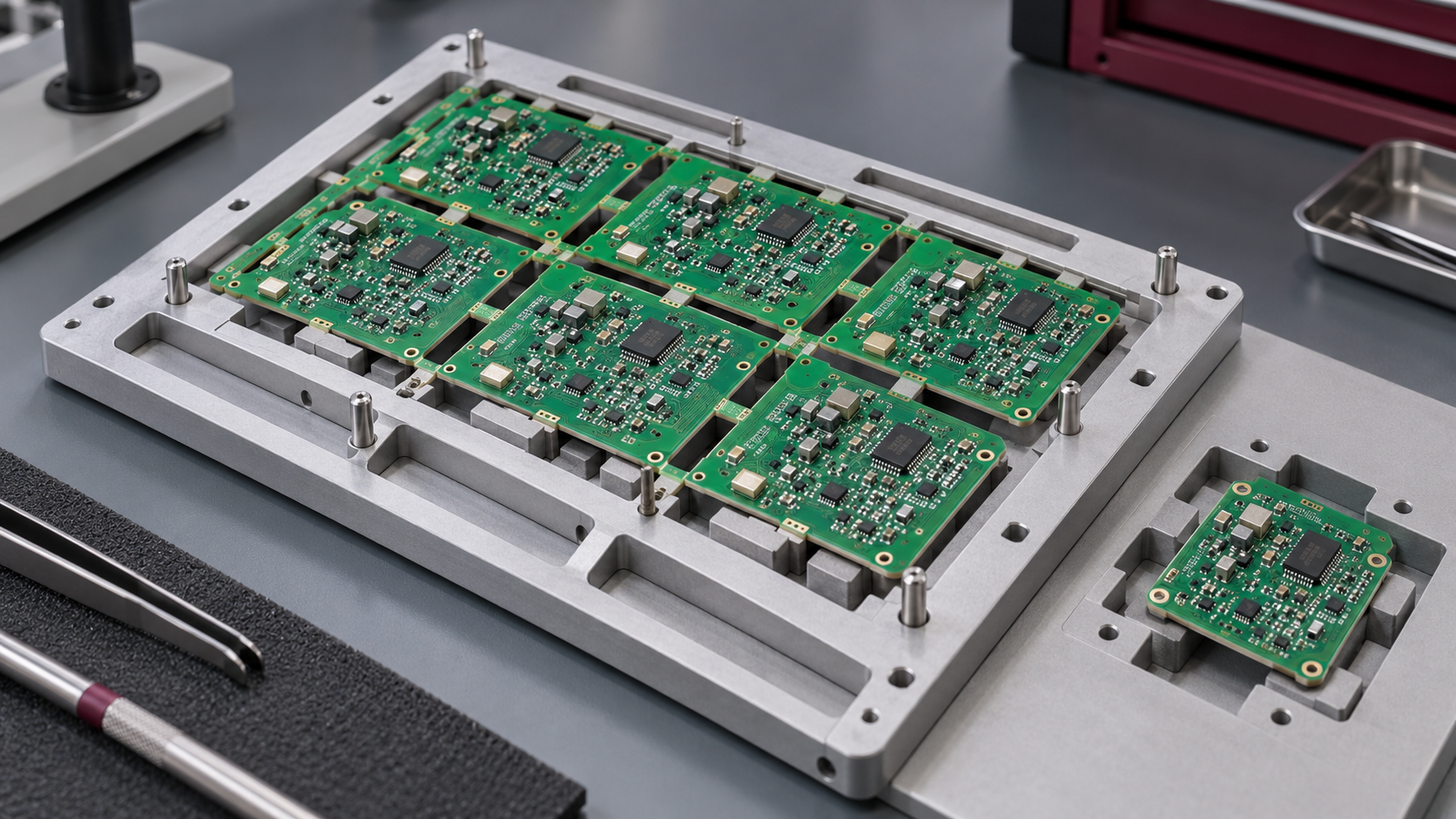
What should a PCB router fixture design review include?
Review panel datums, support beneath every finished board, approved contact areas, cutter and holder access, component pockets, extraction paths and removal after the final tab is cut. Check the fixture against the selected machine and the actual populated assembly. Approve the panel, fixture and toolpath revisions together, then validate the sequence using representative samples before releasing production tooling.
1. Freeze the panel and assembly inputs first
Give the fixture designer the released panel outline, individual board outline, tooling holes, fiducials and tab locations in a common coordinate system. Include the assembly revision and identify the side facing the cutter. A panel drawing alone cannot describe a connector projecting beyond the board edge or a bottom-side component occupying a proposed support location. Link those features to the assembly data before designing pockets or locating pins.
Record which geometry is controlled by the product drawing and which features exist only for manufacturing. A waste rail may provide convenient loading and location, while the finished outline is inspected from a different datum. Make that relationship explicit. If panel variants share a fixture, list their differences and identify the revision combinations covered by the proposal. Similar-looking boards should not automatically share the same tooling approval.
The JELIO technical-support service offers free sample cutting, complete-process video, microscope edge images and dimensional verification. Send the drawing package with representative populated panels so the fixture discussion leads to observable evidence. Use the existing sample-test acceptance checklist for the trial record; this article focuses specifically on what the fixture must locate and support.
| Input | Mark on the drawing | Approval owner |
|---|---|---|
| Panel identity | Part number, panel and assembly revisions, loading orientation | Product / process engineer |
| Location | Datum scheme, tooling holes, fiducials and rail references | Fixture and programming engineer |
| Contact map | Permitted support surfaces and protected components on both sides | Product / quality engineer |
| Separation | Tab IDs, cut sequence, waste rails and finished-board destinations | Process / automation engineer |
| Machine interface | Selected station, mounting concept and extraction connection | Equipment supplier and buyer |
2. Review three support states, not just a loaded panel
In the first state, the intact panel is loaded and located. Check that it seats repeatably on the intended surfaces without relying on a component body as a stop. Identify how an operator or loading device recognizes the correct orientation. Locating features must agree with the released panel geometry rather than forcing a distorted panel into an apparently convenient position.
In the second state, some tabs have already been removed. Trace which connection still restrains each board and which surface supports it. A board can lose support before the final tab if the remaining rail is flexible or a nearby waste section has been removed. Review the planned cut order against the support drawing, particularly for small boards, narrow sections and assemblies with uneven component distribution.
In the third state, all intended cuts are complete. Each individual board and loose waste piece needs a defined resting or receiving position. Describe how boards leave the nest and how remaining rails are removed without catching components. These three states form a practical design review: intact panel, partially separated panel and completed output. The review does not substitute for the actual populated-panel trial.
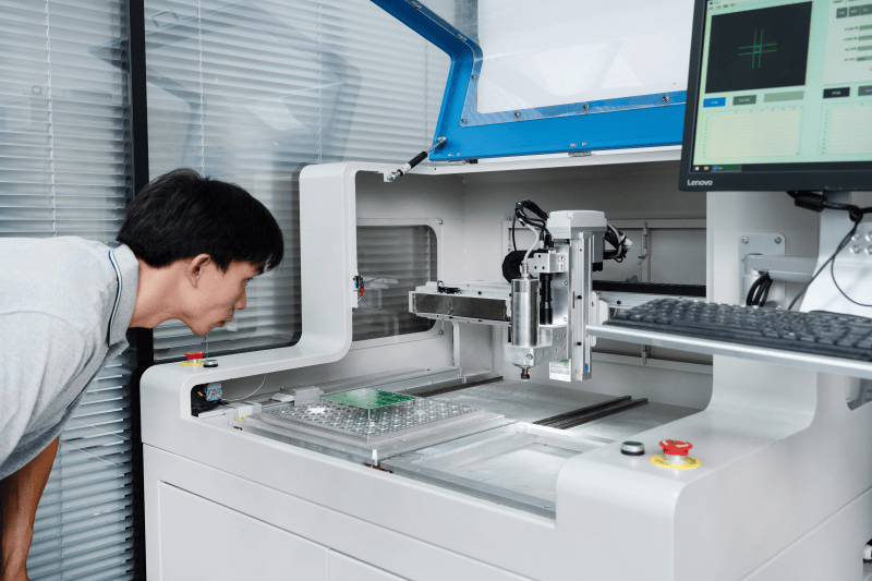
3. Check the full tool assembly and permitted contact areas
Mark a permitted contact map for both faces of the assembly. Include bottom-side components, exposed test points, connector overhangs and any product-specific handling restrictions. A cavity that clears the largest component may still interfere with a solder joint or another feature at its edge. The owner of the product drawing should approve these contact regions; a generic machine envelope cannot make that decision.
Overlay the programmed cutting path with the cutter, holder, local extraction hardware and proposed clamps. Review approach, plunge, exit and travel between cuts as well as the cutting segment itself. Cutter diameter describes only one part of the moving assembly. A clamp clear of the centerline may still obstruct the holder or prevent a board from being removed after cutting.
The JLO-C3532 / JLO-C5045 page lists a spindle tool range and component-height envelope, which are reproduced below from the source catalog. They screen the machine choice; they do not define a universal clearance around every component. Use the companion component-clearance drawing review to record local interference checks for the actual tool and fixture configuration.
4. Keep extraction and changeover in the fixture brief
Locate extraction openings and the route taken by chips and dust through the fixture. Support blocks, component pockets and the chosen cut order can affect access to those openings. Review the extraction arrangement with the machine supplier rather than assuming that a visible opening guarantees the required cleanliness. The application acceptance record should define which board regions are inspected after cutting and how observations are recorded.
The JLO-C3532 / JLO-C5045 product page specifies bottom full suction, with bottom follow-up and top collection listed as options. Keep that option status in the quotation. A fixture designed around one arrangement should be reviewed again when the extraction concept changes. The support drawing, extraction interface and quoted configuration should describe the same machine setup.
For changeover, identify the fixture ID, station assignment, matching program and cleaning access. Ask how the intended mounting surfaces will be checked before loading the next panel revision. If both stations use related programs, record the approved fixture/program pair for each station. Program-copy capability does not by itself establish that two different fixture revisions are interchangeable.
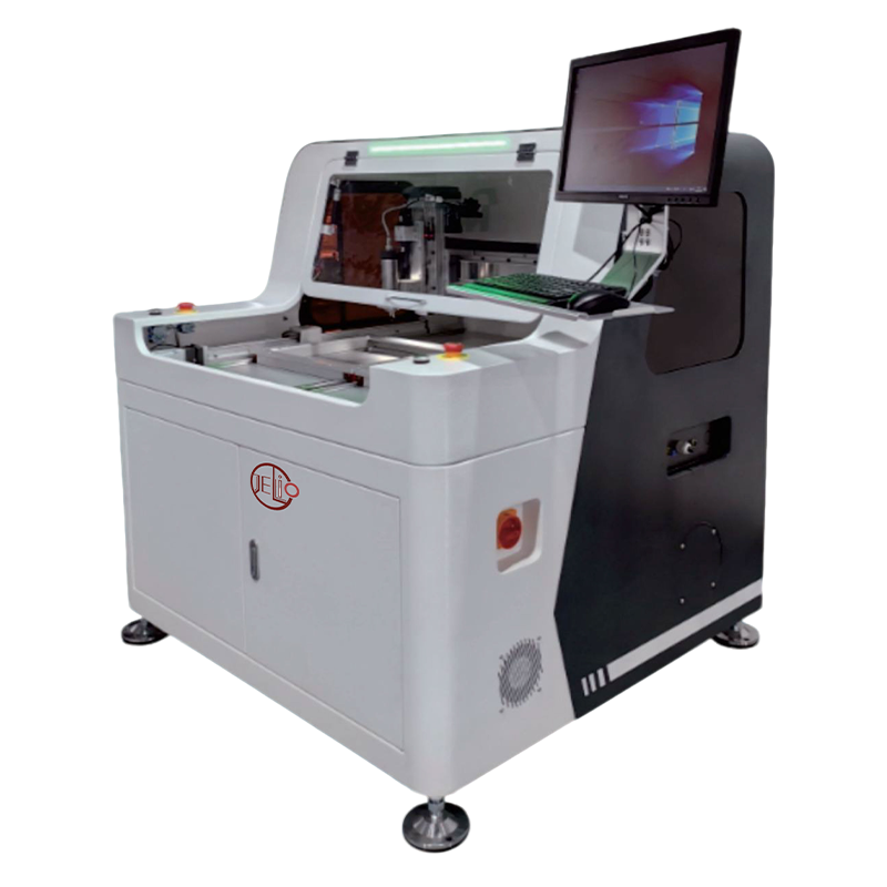
5. Compare fixture concepts using the same work package
Start a concept comparison with the same panel, assembly data and output requirement. Compare a dedicated nest with a reconfigurable support proposal by asking which contact locations are controlled, how separated boards remain supported and what must be changed between variants. These questions produce a meaningful discussion even before prices or cycle observations are available. Avoid substituting a generic flexibility claim for an interface drawing.
Primary tooling sources reinforce this application focus. InsulFab’s routing-fixture overview discusses secure panel holding and manual or automated use. LPKF’s fixture overview addresses holding boards after separation. Neither source defines a JELIO fixture configuration. The worksheet here turns those considerations into named review items for the actual JELIO application.
The ASYS depaneling overview also presents handling and equipment options together. For a buyer, the useful consequence is to compare the complete agreed work package. Record the selected support concept, output arrangement and open engineering actions in the quotation request, while keeping supplier-specific capabilities attached to their own documentation.
6. Release a fixture record your next shift can use
Prepare one controlled release package containing the panel and assembly revision, fixture drawing, tool identification, program revision and sample evidence. Annotate any local clearance issue with its location and disposition. A statement such as “fixture approved” is difficult to reproduce without knowing which panel, which contact surfaces and which sequence were reviewed. Keep corrective changes visible in the revision history.
During the trial, retain an overview of the loaded fixture and photographs of the separated output. Connect the dimensional and edge observations to those same sample IDs. If a support or clamp is moved, update the drawing and repeat the affected checks. The accuracy and repeatability guide explains why a catalog number and an individual board inspection answer different questions.
Before ordering, agree who supplies the fixture, which variants it covers, what documentation is delivered and how later modifications will be approved. Ask JELIO customization support to review requirements that change the standard setup. A concise, controlled fixture brief gives purchasing a concrete scope and gives the production team a record they can use during commissioning and changeover.
Visual review: a held panel versus supported finished boards
Check rails, datums and loading orientation.
Trace the tabs and supports still controlling each board.
Identify the resting position and removal path for every output.
Dedicated nest or reconfigurable support: what must be compared?
| Decision | Dedicated nest proposal | Reconfigurable support proposal |
|---|---|---|
| Board support | Document fixed nests and contact surfaces for each approved variant | Document adjustable locations and how their settings are controlled |
| Component pockets | Review each pocket against the populated assembly | Review every permitted support position against component keep-outs |
| Changeover record | Identify fixture revision and matching program | Identify support layout, settings, program and verification steps |
| Separated output | Confirm every board remains supported | Confirm support remains valid through the complete cut sequence |
| Approval evidence | Trial records for the covered revisions | Trial records for the covered configurations |
Published specifications for the application review
JLO-C3532/JLO-C5045: source catalog values for this product family.
| Parameter | Published value |
|---|---|
| Model | JLO-C3532/JLO-C5045 |
| Number of Workstations | Dual Station |
| Max. PCB Depaneling Size | 350mm(X)*320mm(Y)(Single Station)/500mm(X)*450mm(Y)(Single Station) |
| PCBA Component Height | Upper:15mm Lower:45mm |
| Cuttable PCBA Thickness | 0.5~4mm |
| Spindle Tool Range | φ0.5~3mm |
| Mark Compensation | Camera recognition & positioning, automatic compensation |
| Dust Collection Method | Bottom full suction, bottom follow-up dust collection (optional), top dust collection (optional) |
From panel drawing to a controlled fixture release
- 01
Define the workpiece
Freeze panel, assembly, datum and variant information.
- 02
Map contact and access
Review supports, pockets, cutter assembly and extraction interfaces.
- 03
Trace the cut sequence
Check intact, partially separated and completed-board states.
- 04
Run representative samples
Retain linked setup photographs, process video and inspection records.
- 05
Release the agreed scope
Approve fixture/program revisions, covered variants and quotation responsibilities.
Frequently asked questions
Can one fixture be used for several PCB variants?
It can be proposed where the approved location, contact map, component pockets and tool access remain suitable for every listed variant. Keep a variant matrix and identify the corresponding fixture/program revisions. Validate the covered combinations rather than approving reuse only because outer panel dimensions match.
Does a locating pin replace support beneath individual boards?
Location and support answer different questions. A pin establishes a reference where the drawing permits it; the fixture must also control each finished board through the cut sequence and after separation. Review the remaining restraints and resting position rather than relying on the intact panel alone.
What clearance should I leave around the cutter?
Use the actual cutter and holder geometry, local extraction hardware, proposed clamps and assembly layout. The machine tool range is a screening input. Have the supplier review the complete moving envelope and the relevant tolerance stack instead of applying an unsourced universal clearance.
Should the fixture be reviewed when extraction changes?
Yes. A change between the catalog extraction arrangements can affect openings, supports and local hardware. Review the affected fixture and toolpath interfaces, preserve the selected option in the quotation and repeat the relevant sample checks before releasing the revised setup.
What should I send JELIO for a fixture quotation?
Send the released panel and assembly drawings, component heights, contact restrictions, proposed cut sequence, representative samples and intended output handling. Identify the selected machine family and ask for the fixture scope, revision coverage, sample deliverables and outstanding engineering actions to be recorded.
Related equipment and guides
Request a fixture and sample-cutting review
Send JELIO your panel and assembly revisions, contact map and output arrangement so the review addresses the proposed fixture and machine together.
Request a fixture and sample-cutting review →