

JELIO ENGINEERING INSIGHTS
PCB Router Cutter Selection: Diameter and Toolpath Review
PCB router cutter selection is a joint decision about the board material, the cutting edge and the programmed path. A tool that fits a nominal slot can still be unsuitable when its working length, holder access or entry movement is checked against a populated panel. This guide gives EMS process engineers a practical way to compare candidate cutters before ordering a production setup. It connects a selection register to the published JELIO JLO-C3532 / JLO-C5045 tool range, then shows what to include in a representative sample-cutting request. The deliverable is a controlled cutter-and-program record rather than a universal diameter or speed recommendation.
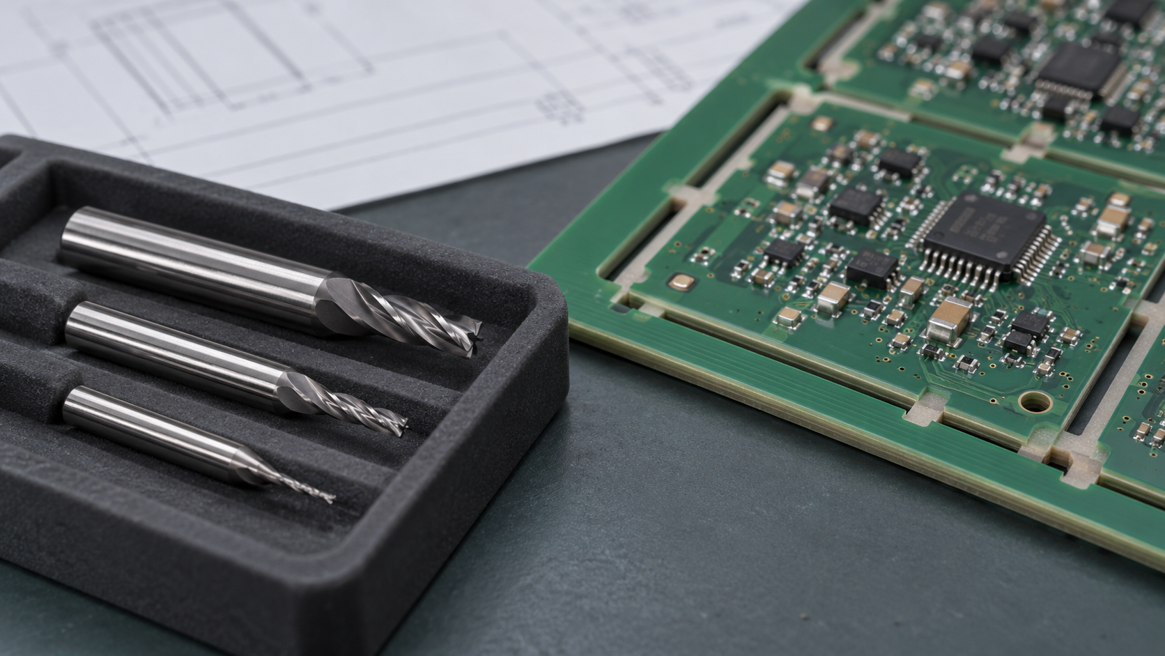
How should you choose a PCB router cutter?
Start with the actual laminate and panel drawing, then compare cutting diameter, working length, shank and holder compatibility with the selected machine. Review the complete toolpath, including entry, corners and exit, against components and fixture hardware. Select candidates with the equipment and tooling suppliers, run representative populated panels, and release the approved cutter identification with its program revision and inspection record.
1. Specify the material and the cut before the cutter
Start the request with the laminate designation, finished panel thickness, assembly revision and intended separation task. Identify whether the path removes connecting tabs, completes a contour or follows a previously routed channel. Include copper and other layers relevant to the proposed cut. A material description such as “PCB” leaves the tooling supplier without the information needed to distinguish applications.
GCT’s depaneling application guidance distinguishes tooling for different substrate families. The useful buying lesson is to make the material explicit in the inquiry, rather than carry one cutter choice across every assembly. On the JELIO product page, cutting aluminum substrates calls for replacement with the dedicated spindle. Keep that configuration requirement attached to the application discussion instead of treating the standard setup as interchangeable.
Send the same material and drawing package to the machine supplier and the cutter supplier. Record who selects the cutter and who approves the resulting program. If a material substitution occurs later, identify the affected selection record and review it again. This makes a repeat order traceable without claiming that two visually similar panels require the same cutting conditions.
2. Separate cutting diameter, shank and working length
Cutting diameter describes the edge that removes material; shank diameter describes the holding interface. Usable working length describes where the tool can actually cut in the proposed setup. Keep these as separate drawing or catalog fields. Also identify the tool part number, cutting geometry and supplier revision. Ordering only by a diameter can leave the holding and engagement details unresolved.
The JLO-C3532 / JLO-C5045 catalog lists a spindle tool range of φ0.5~3mm. Use that exact published range as a machine-screening input, then ask for confirmation of the proposed cutter and holding arrangement. It is not a statement that every cutter with an edge diameter in that range fits every collet, panel geometry or extraction arrangement.
Check the usable cutting section against the board stack and the proposed cutting levels. Include the holder projection and the fixture below the board in the review. A longer protruding tool should not be selected merely to bypass an access problem without discussing the setup with the suppliers. The approved record should identify the physical tool arrangement used during the trial, not just its nominal size.
3. Review the path that the selected diameter creates
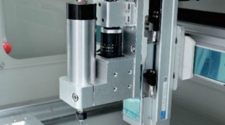
Ask the programmer to distinguish the finished-board boundary from the cutter centerline. A compensated path depends on the selected cutting diameter and the side of the contour being machined. When a candidate diameter changes, review those program assumptions before cutting again. Include internal corners and narrow channels; a tool can travel along a straight section yet fail to produce the intended local shape.
Follow the entire motion sequence: approach, entry, tab removal, travel between segments and exit. Review both the cutting tip and the surrounding holder and extraction hardware. Mark the locations where nearby components, clamps or fixture walls govern access. The companion component-clearance review covers that local interference register, while this worksheet records which cutter-and-path combination was evaluated.
Check what supports each individual board when the final tab is removed. If the cut sequence or entry point changes with the cutter proposal, review the support state as well. Use the fixture design guide for contact and support details. This keeps tool selection connected to the actual assembly without repeating a general machine-selection comparison.
4. Treat spindle limits and cutting recipes differently
A maximum spindle speed is an equipment limit, not an instruction to run every tool at that setting. The same applies to the catalog cutting-speed range. Ask the tooling supplier for a recommendation tied to the exact tool and material, then have the machine supplier review it for the proposed setup. Record speed, feed, entry method and cutting levels together so a trial can be repeated.
IND-SPHINX’s router application chart separates router geometries and application categories. It provides a useful reminder that diameter alone does not describe a cutting tool. Use the manufacturer’s current tool documentation for the candidate part; do not copy a different manufacturer’s numerical recipe into a JELIO machine specification.
JELIO’s product description includes tool-usage management based on cutting-edge length and PCBA thickness, with actual service-life recording. Ask how the selected cutter is entered into that system and how its cutting sections are assigned. Record observed trial information separately from the initial setting. A configured life counter is a process control input, while an accepted replacement interval needs evidence from the relevant application.
5. Keep a cutter-selection register with the sample
Use one row per candidate and link each row to its supplier part number, drawing revision and program revision. Attach the tool data sheet rather than transcribing only the easiest fields. This record allows quality and procurement colleagues to see why a candidate was retained or rejected, and lets the next shift identify the approved replacement without relying on a photograph alone.
Before the trial, define the edge regions and finished dimensions to inspect. Identify the panel and sample boards used, and retain setup photographs showing tool projection and support. During the trial, record actual settings and any interruption or manual adjustment. A useful result identifies what changed between candidates, rather than comparing two boards produced under unrelated conditions.
| Record | What to capture | Decision supported |
|---|---|---|
| Material and panel | Laminate, thickness, panel and assembly revisions | Whether the candidate addresses this workpiece |
| Tool identity | Manufacturer, part number, cutting geometry and coating if specified | An orderable and traceable replacement |
| Geometry and interface | Cutting diameter, shank, usable length and approved holding setup | Fit and accessible cutting envelope |
| Program and settings | Path revision, offsets, entry method and actual trial settings | A reproducible cutter-and-path combination |
| Inspection | Sample IDs, edge images, dimensional results and disposition | Release or a specific follow-up action |
6. Compare samples, then release the complete combination
Change one identified selection variable at a time where practical, or document every difference when a combined change is necessary. Use representative populated panels and the agreed fixture. Compare the specified edges and dimensions, retained debris observations and any interrupted cuts. Avoid ranking cutters from an attractive photograph of a single edge while overlooking a difficult corner elsewhere on the panel.
JELIO technical support offers free sample cutting, complete-process video, microscope edge images and dimensional verification. Request those deliverables against the candidate register. The sample-test checklist helps define the acceptance record. The result should name the selected tool, approved program and applicable panel revisions, with any outstanding action assigned to an owner.
Release the replacement part reference and the conditions that trigger another review: a different material, changed thickness, revised tab geometry, new holder or extraction setup, or a substituted cutter. Keep the original trial record available to service personnel. For replacement workflow and procurement scope, continue to the manual versus automatic tool-change comparison.
Visual comparison: cutter size and the path review
Review narrow-channel access, usable length and its own approved recipe.
Review corner geometry, path compensation and surrounding clearance.
Attach the selected tool to the panel, fixture and program revisions.
Smaller or larger cutter: compare decisions, not assumed performance
| Review item | Smaller-diameter candidate | Larger-diameter candidate |
|---|---|---|
| Channel and contour | Check the narrowest path and intended corner shape | Check that the swept cut still fits the approved contour |
| Holding interface | Confirm shank and holder compatibility | Confirm shank and holder compatibility independently |
| Cutting length | Check the available cutting section and projection | Check the available cutting section and projection |
| Program | Review compensation and entry for this diameter | Review compensation and entry again after changing diameter |
| Trial outcome | Inspect the same defined edges and dimensions | Inspect the same defined edges and dimensions |
| Purchase release | Name the approved supplier part and program revision | Use only if this combination passes the agreed review |
Published specifications for the application review
JLO-C3532/JLO-C5045: source catalog values for this product family.
| Parameter | Published value |
|---|---|
| Model | JLO-C3532/JLO-C5045 |
| Spindle Tool Range | φ0.5~3mm |
| Spindle Speed | MAX.60000rpm |
| Spindle Power | 400W |
| Cuttable PCBA Thickness | 0.5~4mm |
| Cutting Speed | 0~100mm/sec |
| Cutting Function | Straight line, L-shape, U-shape, circle, arc, etc |
| Milling Cutter Replacement Method | Manual tool change / Automatic tool change (optional) |
| Dust Collection Method | Bottom full suction, bottom follow-up dust collection (optional), top dust collection (optional) |
Cutter selection to production release
- 01
Describe the workpiece
Freeze material, panel, assembly and separation-task inputs.
- 02
Shortlist tools
Obtain exact cutter geometry and supplier recommendations.
- 03
Review the program
Check compensation, complete motion and fixture access for each candidate.
- 04
Run representative panels
Record actual setup, full-process video and defined inspection results.
- 05
Release and identify
Approve the tool, program and replacement reference together.
Frequently asked questions
Does a narrow PCB slot automatically require the smallest cutter?
No. Review the actual channel, intended finished contour, usable cutting length and complete tool assembly. Select a compatible candidate with the suppliers and validate the resulting path. A nominal slot width alone does not approve the holder, entry movement or cutting recipe.
Is maximum spindle speed the correct setting for every cutter?
No. The catalog maximum defines the machine limit. The operating recommendation must address the selected tool, material and setup. Record the approved settings from the application trial rather than turning a maximum equipment value into a universal recipe.
What changes in the program when cutter diameter changes?
Review cutter compensation, the resulting centerline, internal corners, entry and exit, and the relationship to components and fixture hardware. Record the new cutter with the program revision and repeat the affected sample checks before releasing that combination.
Can the optional diameter inspection replace a sample trial?
The JLO-C3532 / JLO-C5045 page describes optional visual inspection of blade diameter against the software setting. Specify that option when required. The panel trial still addresses material behavior, access, edge condition and dimensional acceptance for the actual application.
What should I send for a cutter application review?
Send panel and assembly drawings, material and thickness information, tab locations, candidate tool data sheets, fixture details and representative populated samples. Identify the intended JELIO model and request a recorded review of the cutter, program and inspection results.
Related equipment and guides
Request a cutter and toolpath sample review
Send your panel, assembly revision and candidate tool data so JELIO can review the machine setup and sample-cutting evidence with you.
Request a cutter and toolpath sample review →