

JELIO ENGINEERING INSIGHTS
PCB Depaneling Component Clearance: Drawing Review
PCB depaneling component clearance is a three-dimensional drawing question, not simply a distance from a footprint to the finished board edge. A tall connector, an underside component or the tool holder can control access even when the cutter itself appears to fit. This guide helps quality and process engineers prepare a segment-by-segment clearance review before requesting routing or combined router-and-saw equipment. It compares relevant published JELIO model envelopes, separates machine screening from local application approval and provides a register for recording the actual decision. Use it with the released populated-assembly data and a defined fixture concept, then carry the reviewed configuration into sample cutting.
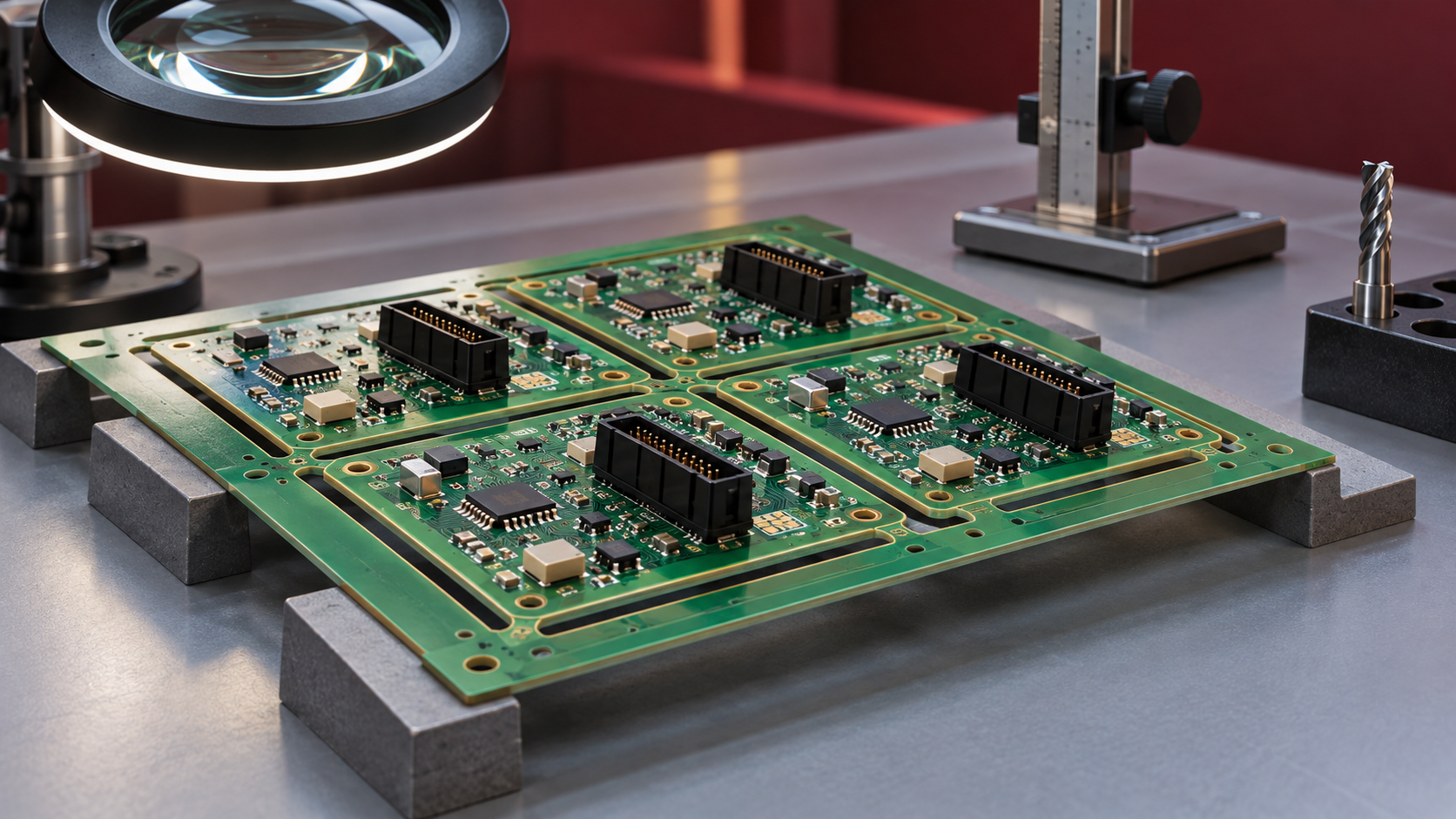
How much component clearance is needed for PCB depaneling?
Determine clearance from the actual cut path, component geometry on both sides, cutter or saw assembly, fixture and handling arrangement. A machine’s component-height limit screens one dimension; it does not specify the minimum edge gap for every assembly. Review the moving envelope and relevant tolerances for each cutting segment, then validate the selected configuration with representative populated samples.
1. Build a three-dimensional review package
Start with the finished outline and panel layout, then add the populated top and bottom assembly information. Identify connector housings, component bodies, fasteners and features projecting beyond the nominal board edge. Where the assembly model is incomplete, request the controlling drawing or physical sample for that feature. A silkscreen or placement centroid does not describe the space occupied by the complete part.
Keep the panel revision, assembly revision and component variant together. The same bare board can carry different connector heights or optional components. Record those variants in the review package and mark which ones the proposed fixture and program must cover. Include the orientation in which the assembly will be loaded, because reversing the board changes the relationship between components, support surfaces and moving hardware.
Use the fixture-design review to identify the contact map and support concept. Then add the tool information for the intended machine. For a supplier review, send these documents together through JELIO technical support. That service lists sample cutting and dimensional verification, making it a practical next step after the drawing questions have been organized.
| Register field | What to record | Decision supported |
|---|---|---|
| Segment and revision | Cut ID, panel/assembly revision and board orientation | Which geometry is under review |
| Component feature | Reference, body geometry, side, height and overhang | What occupies the local working volume |
| Process and tool | Routing or saw segment, proposed tool and holder | Which moving envelope must be checked |
| Fixture and handling | Support, clamp, extraction hardware and removal direction | Which nearby interfaces may interfere |
| Disposition | Accepted configuration or open action, owner and revision | What can proceed to the sample trial |
2. Keep component height separate from edge distance
The machine’s component-height specification describes an equipment envelope for the stated family. The local edge-clearance question asks whether the selected moving assembly can reach a particular cutting segment without interference. Passing the first screen does not resolve the second. Likewise, a generous visible edge gap does not resolve an underside component conflicting with the fixture.
JELIO publishes Upper:15mm Lower:45mm for the JLO-C3532 / JLO-C5045 router family and Upper:10mm Lower:45mm for the JLO-CXJ3235 / JLO-CXJ4550 integrated family. Those values are reproduced from their own catalog property records in the comparison table below. Keep the upper/lower labels and model pairings intact rather than simplifying the two families to one generic component-height claim.
Next, review the component position relative to the cutting direction, the fixture datum and the actual tool assembly. Include the relevant drawing and setup tolerances in the supplier’s assessment. This article intentionally supplies no universal minimum edge gap: that decision belongs to the populated assembly and selected process. Record the accepted configuration or the engineering action needed to resolve the segment.
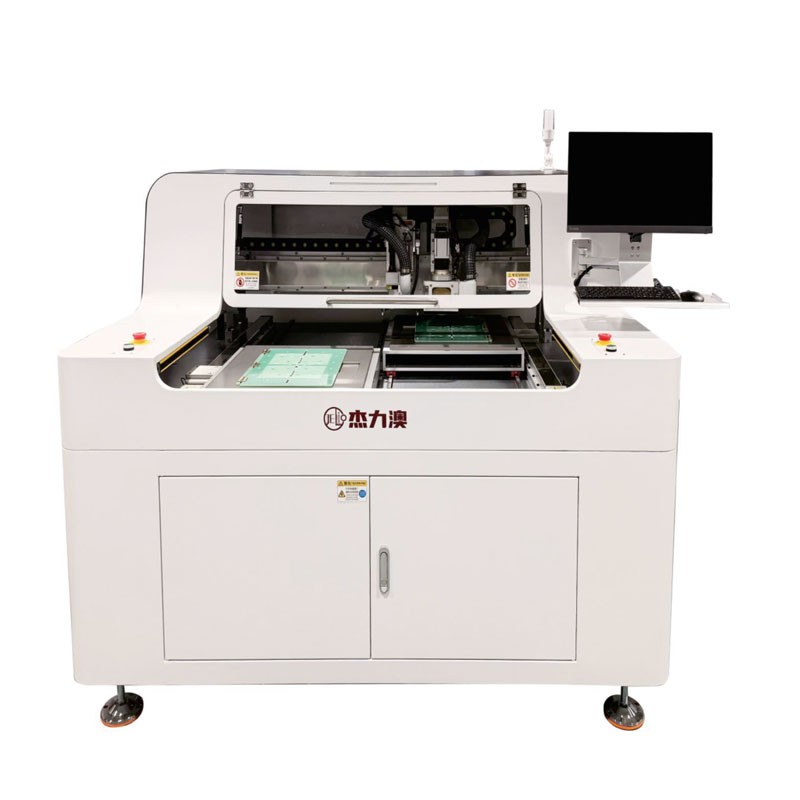
3. Review more than the router cutter diameter
For a routing segment, start with the programmed centerline and the selected cutter geometry. Continue the review upward to the holder and adjacent extraction hardware, and downward to the fixture pocket. Check the approach, plunge, curved section and exit. A collision-free line in a flat drawing can still conflict with a tall housing during the approach or with a support feature below the board.
The JLO-C3532 / JLO-C5045 catalog lists the spindle tool range as φ0.5~3mm. That is a tool selection envelope, not a specified safe gap between every component and the board edge. Identify the proposed cutter and its working arrangement for the application, then have the supplier review access together with the fixture and extraction configuration.
Do not resolve an interference solely by moving the cutting path unless the resulting finished outline remains within the released drawing. If a different cutter, approach or fixture is proposed, record the revision change and the affected segments. Quality, process engineering and the supplier should review the same configuration so that the eventual sample evidence answers the original product requirement.
4. Treat saw segments as their own access problem
On a combined router-and-saw machine, record which segments use each process. The JLO-CXJ3235 / JLO-CXJ4550 page lists straight-line cutting for the saw and a wider set of line and curved functions for the milling cutter. Use those published functions to organize the drawing review; do not assume a saw proposal can follow the same curved contour as the router.
For the saw, review the blade and surrounding assembly along the entire intended movement, including entry and exit. Components or handling features outside the finished-board outline can still occupy that path. The catalog’s blade thickness and diameter help identify the proposed equipment, but they do not independently establish the project’s kerf allowance, local gap or finished-outline result.
If an assembly requires both routing and sawing, preserve the sequence and the support state between processes. A board partly released by one operation may need a different restraint during the next. Ask for the fixture and program to be reviewed as a complete sequence. Keep unresolved interference items open instead of treating the availability of two cutting methods as automatic application approval.
5. Include the fixture, waste rail and removal path
A clearance register should identify nearby clamps, locating features and component pockets as well as moving tools. Check whether the intended contact surfaces remain available on all variants. For a component that overhangs a board edge, review both its final position in the nest and the path taken when the board is lifted or transferred. The removal motion can expose a constraint not present during the cut.
Trace the waste rail and detached pieces through the sequence. Identify where they rest and how they are removed without crossing protected components. When extraction hardware or support positions change, reopen the affected segments. A photograph of an intact panel is useful context, but the completed-board state and output handling also need to match the reviewed concept.
For procurement, turn these findings into named quotation items. Specify the covered assembly variants, intended process assignment, fixture responsibility and output arrangement. If a requirement changes the standard concept, use customization support before finalizing the comparison. This keeps the purchasing discussion connected to the geometry that engineering actually approved.
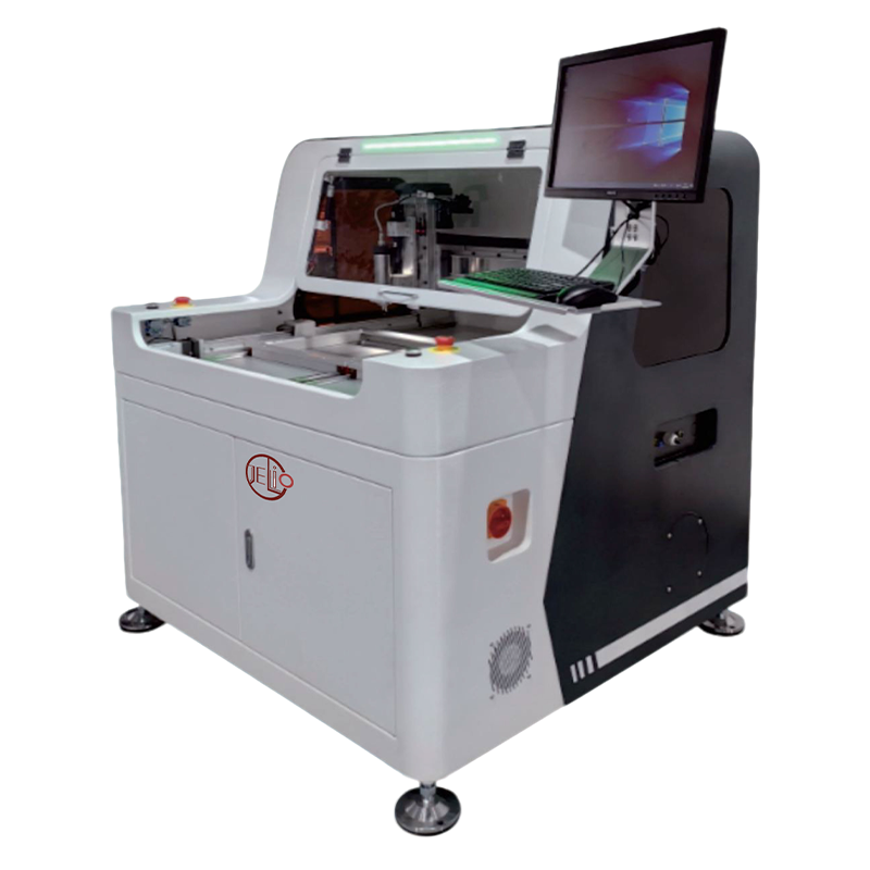
6. Turn reference guidance into a controlled sample review
The LPKF panel-design guide discusses component geometry and separation method together. Its process-specific examples are useful context, not transferable JELIO clearance limits. The Cencorp depaneling overview similarly presents equipment selection with production and handling options. The register above adds a concrete, segment-level decision record for this application.
After drawing review, select populated samples that represent the critical features and the listed variants. Ask for setup photographs and process video linked to the tool, fixture and program revisions. Use the sample-test checklist to agree the edge and dimensional observations. Keep any project-specific inspection criteria with the controlling product drawing and trial brief.
Finally, issue a disposition for each critical segment: accepted with the recorded configuration, revise and review again, or evaluate another process. Retain the open-action owner and evidence needed to close the issue. The resulting package lets quality explain what was checked and lets purchasing compare a quotation against that same scope, without turning a general catalog capability into an unsupported sample result.
Three review layers that answer different questions
Compare published panel, thickness and component-height envelopes.
Review the tool assembly, components, fixture and relevant tolerances.
Inspect identified samples and retain the configuration and observations.
Router and integrated-family catalog screening comparison
| Parameter | JLO-C3532/JLO-C5045 | JLO-CXJ3235/JLO-CXJ4550 |
|---|---|---|
| Model | JLO-C3532/JLO-C5045 | JLO-CXJ3235/JLO-CXJ4550 |
| PCBA Component Height | Upper:15mm Lower:45mm | Upper:10mm Lower:45mm |
| Max. PCB Depaneling Size | 350mm(X)*320mm(Y)(Single Station)/500mm(X)*450mm(Y)(Single Station) | 320mm(X)*350mm(Y)(per station)/450mm(X)*500mm(Y)(per station) |
| Cuttable PCBA Thickness | 0.5~4mm | 0.5~4mm |
| Cutting Accuracy | ±0.05mm | ±0.05mm |
Published specifications for the application review
JLO-CXJ3235/JLO-CXJ4550: source catalog values for this product family.
| Parameter | Published value |
|---|---|
| Model | JLO-CXJ3235/JLO-CXJ4550 |
| Number of Workstations | Dual Station |
| PCBA Component Height | Upper:10mm Lower:45mm |
| Milling Cutter Tool Range | φ0.5~3mm |
| Saw Blade Tool Range | Saw blade thickness:0.3mm; diameter:100mm |
| Milling Cutter Cutting Function | Straight line, L-shape, U-shape, circle, arc, etc |
| Saw Blade Cutting Function | Straight line |
| Mark Compensation | Camera recognition & positioning, automatic compensation |
A clearance decision workflow for the populated assembly
- 01
Identify critical segments
Link each cut and component feature to the released assembly revision.
- 02
Screen the model
Read panel, height, thickness and tool limits from the selected source page.
- 03
Review the moving envelope
Check tool, holder, fixture, extraction and approach or removal paths.
- 04
Resolve and record
Name the accepted setup or the action owner for every interference item.
- 05
Validate populated samples
Keep sample observations linked to the reviewed tool, fixture and program.
Frequently asked questions
Can the machine’s upper component-height limit be used as an edge-clearance rule?
No. Height is one machine-screening parameter. A component-to-edge decision also depends on position, tool and holder geometry, fixture, extraction hardware and the relevant tolerances. Keep the catalog envelope separate from the segment-level application decision and its sample evidence.
Do I need bottom-side assembly data if the cutter is above the PCB?
Yes. Bottom-side components can affect support pockets, contact areas and the position in which the board seats. Provide both faces and identify the loading orientation so the fixture and tool review uses the complete populated assembly rather than only its visible top surface.
Can the same clearance decision cover a router cut and a saw cut?
Review each process and segment independently. The integrated JELIO catalog lists different cutting functions and tool information for routing and sawing. Preserve the process assignment, movement and support state in the program review; a clearance decision for one arrangement does not automatically approve the other.
What should happen when a connector changes after the fixture is ordered?
Update the assembly variant and check affected contacts, tool approaches and removal paths. Record whether the existing fixture and program remain suitable or require revision. Repeat the relevant review and sample checks before extending the approved scope to the changed assembly.
What should I request before placing a machine order?
Request a written configuration tied to the reviewed panel and assembly revisions, tool and fixture concept, process assignment, sample deliverables and remaining engineering actions. Include the accepted clearance register so the equipment quotation and subsequent acceptance review address the same project scope.
Related equipment and guides
Discuss your populated-panel drawing
Share the panel and assembly drawings, critical component features and proposed cut segments with JELIO for an application and sample-cutting review.
Discuss your populated-panel drawing →